
Protection Testing Bulletin
The mission of the Protection Testing Bulletin is to provide a collection of unbiased technical documents (i.e., application notes, PowerPoints, and technical papers), all relating to protection testing. This page is updated regularly, available at any time, and shareable with your colleagues and network!
If you haven't already, join our mailing list to stay up-to-date when new information is released. As this content is focused on applications within Canada and the US, we ask only North American residents to subscribe. We welcome anyone to view the page.
Feature Video
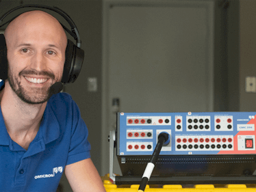
Safe and efficient polarity check during commissioning
Wiring and polarity check is a key task performed during commissioning of protection and control systems. This video shows a safe and efficient polarity check during commissioning of a substation at National Grid, USA using the COMPANO 100.
Our Articles
FAQs
Dear OMICRON Technical Support, I am getting failed results for phase distance zone 2 testing points. The relay trips with no delay and the SOTF LED in the relay comes on.
The SOTF (Switch-Onto-Fault) logic is used to quickly trip in case the circuit breaker is closed onto a fault condition, protecting maintenance personnel and substation equipment. Depending on the relay logic, the relay may determine a breaker close command was issued if it sees a jump from no current to high current values. This is what happens when we perform a test with no load current during the pre-fault state, therefore the SOTF logic will be enabled and initiate an instant trip. To overcome this logic, a load current should be applied during pre-fault. If using the Advanced Distance module, enable and set a Load current at the Test View Settings tab. Make sure the Prefault time duration is enough to overcome the SOTF logic. If using any other module (e.g. State Sequencer), make sure current is applied during the pre-fault state.
In the Overcurrent test module, I can set up and test a negative sequence element. I see that OMICRON defines the current signal as “I2,” but my SEL settings use “3I2.” How can I account for this in Test Universe?
Protection is a universal concept; however, every relay manufacturer has their own way of defining protection through their settings... Show full answer219 kB
In your ARCO Control software, I see that you have all the TCC 113 curve, however my controller is programmed for a KYLE 113 curve. Is there a difference? If so, where do I find the KYLE curve?
The TCC curves stand for Time Current Characteristic and are equation-based curves which are provided by the manufacturers of the recloser controllers... Show full answer309 kB
The print-to-pdf seems to always cut things from the test report. Is there a way to make the print-to-pdf file look nicer?
You can preview the print-to-pdf file by clicking anywhere on the test report area and then selecting the Print Preview option from the test plan File menu... Show full answer384 kB
Attend our Academy Courses
Protection Testing Classes