Grounding Systems
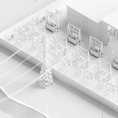
Understanding Your Grounding System’s Condition
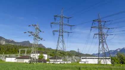
Grounding systems, also known as earthing systems, are vital to the safe and reliable operation of your power system. During a fault, fault current and ground (earth) impedance cause potential to rise (GPR/ EPR), creating step and touch voltages that may be hazardous.
Systematic testing helps you verify that your ground grids safely dissipate fault currents, protecting your personnel and assets.
The measurements from ground impedance, step and touch voltages, soil resistivity, and ground grid continuity, provide the confidence you need during planning, commissioning, and maintenance.
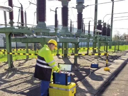
Ensuring Personnel Safety and System Integrity
Personal Safety
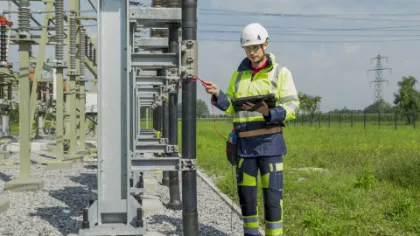
In the event of a system fault, elevated ground potential can lead to hazardous step and touch voltages. Personnel safety cannot be ensured without verified measurements, especially in and around substations or near metallic structures with transferred potentials.
Aging Infrastructure
Corrosion, mechanical stress during faults, and improper construction can increase ground impedance or interrupt ground grid continuity. Deterioration may remain undetected unless periodic high-current continuity tests and impedance measurements are performed.
Neutral point treatment changes
When you convert a resonance grounded network to solid grounding – often required due to high shares of underground cables – earth fault currents usually take on a significant increase.
Measurements can help you verify that the potential resulting from step and touch voltages are still within permissive limits.
Rising fault currents
As more renewable energy sources are connected to the grid, combining distributed generators and the higher load currents along transmission lines could lead to higher fault currents.
This can increase ground potential rise, leading to higher, potentially dangerous step and touch voltages.
Testing Methods
Grounding Systems Measurement Methods
Ground impedance measurement
Ground impedance measurement
Ground impedance describes how well your grounding system connects to the surrounding soil. An increased value indicates deterioration. During a fault, the combination of fault current and ground impedance causes a Ground or Earth Potential Rise (GPR, EPR).


Step and touch voltage measurement
Step and touch voltage measurement
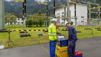
Step and touch voltages occur when potential differences arise in a substation or when one is too close to the grounding system during a fault in a power line or in the power system. Performing the measurement to verify that critical potential differences haven’t occurred, may endanger the human body.
SRT
Soil resistivity test
An electric soil resistivity test (SRT) is performed before constructing a grounding system. The soil’s electric resistivity is required when designing a grounding grid that meets all safety and functional criteria. The Wenner or Schlumberger methods are typically used for this measurement.
Ground grid continuity test
Ground grid continuity test
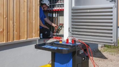
A ground grid must reliably conduct the full fault current. A high-current resistance measurement can be used to check the ampacity between different parts of the system, such as risers and grounding points. This method can detect faulty construction work and deterioration at an early stage.
Ground impedance measurement
Ground impedance describes how well your grounding system connects to the surrounding soil. An increased value indicates deterioration. During a fault, the combination of fault current and ground impedance causes a Ground or Earth Potential Rise (GPR, EPR).
Step and touch voltage measurement
Step and touch voltages occur when potential differences arise in a substation or when one is too close to the grounding system during a fault in a power line or in the power system. Performing the measurement to verify that critical potential differences haven’t occurred, may endanger the human body.
Soil resistivity test
An electric soil resistivity test (SRT) is performed before constructing a grounding system. The soil’s electric resistivity is required when designing a grounding grid that meets all safety and functional criteria. The Wenner or Schlumberger methods are typically used for this measurement.
Ground grid continuity test
A ground grid must reliably conduct the full fault current. A high-current resistance measurement can be used to check the ampacity between different parts of the system, such as risers and grounding points. This method can detect faulty construction work and deterioration at an early stage.
Recommended Solutions
Find The Right Solution for Your Application
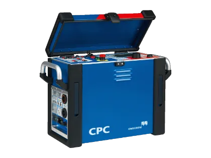
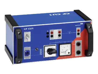
CPC 100 + CP CU1 + HGT1
This multifunctional test set supports comprehensive condition assessments of medium and large-sized grounding systems. It offers a wide dynamic range and high sensitivity, enabling you to measure very small voltages and clearly distinguish them from interference and disturbances.
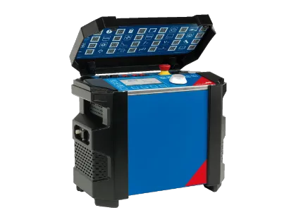
COMPANO 100 + CIB1 + HGT1
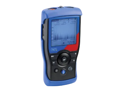
This solution is a portable, battery-operated test set for primary and secondary injection and basic protection testing, suitable for medium-sized grounding systems. It allows you to connect medium-voltage current-injection cables and can also measure cable impedance and shield current.
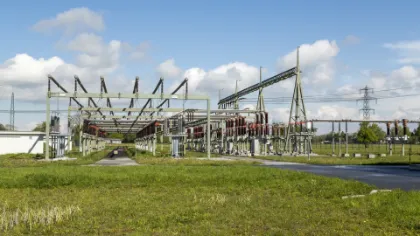
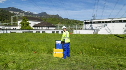
COMPANO 100 + HGT1
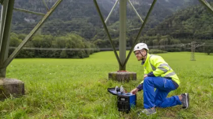
This test set is recommended for small grounding systems, like small substations and transmission towers. It is a portable, battery-operated solution for primary and secondary injections and basic protection testing. It’s suitable for performing ground impedance, soil resistivity, continuity, and step and touch voltage measurements.
Safety Compliance
EN 50522, IEEE 81 and IEEE 80/81 define maximum earth potential rise and permissible step and touch voltages based on the duration of a single-phase fault. Complying with these standards helps ensure that dangerous voltage levels in and around substations are avoided during real faults, protecting people and animals from harm.
Related Products
Related Videos


Energy Talks
Related Podcast Episodes



What is ground impedance and why is it important?
Ground impedance describes the connection quality between a grounding system and the surrounding soil. It directly influences ground potential rise during a fault, affecting personnel safety.
How are step and touch voltages evaluated?
Measurements are performed in and around the grounding grid and the results are assessed in accordance with EN 50522 or IEEE 80/81 safety limits.
What’s the difference between power line injection and current probe injection?
Power line injection requires a disconnected, remotely grounded line to simulate realistic fault-current distribution. This method is ideal for large substations. Current probe injection is often easier to perform on smaller grounding systems and transmission towers.
When should grounding systems be tested?
Soil resistivity measurements should be performed to obtain the required resistivity data for planning a new grounding system. During commissioning, compliance with applicable standards should be verified. During maintenance, periodic condition assessments should be performed to ensure long-term safety and system reliability.
What is the fall-of-potential (FOP) method?
The FOP test measures the voltage between a grounding system and a remote reference point at increasing distances. This determines the true resistance to earth and gives you the expected potential rise, known as the earth potential rise (EPR) or ground potential rise (GPR).
What’s the difference between the Wenner and Schlumberger Methods?
The Wenner method places all four test probes in a straight line with equal spacing between them, making it simple and easy to set up.
The Schlumberger method also uses four probes, but the distances are unequal. Different depth measurements only require two probes to be moved, making this method more efficient for detailed soil investigations.
When should soil resistivity be measured?
Soil resistivity should be measured during the planning and design phase of a grounding system, before construction begins. It provides the essential data needed to correctly dimension a grounding grid and meet safety and functional requirements during fault conditions.
Looking for some guidance on this topic?