Switchgear

Confidence in Every Trip: Your High-Voltage Switchgear
Circuit breakers, grounding switches, and disconnectors form the backbone of a reliable power system. Proactive maintenance and preventive measures, enable you to manage environmental influences, aging, and operational challenges effectively. This approach minimizes disruptions, avoids major outages, and ensures long-term system performance and stability.
Testing Methods
High Voltage Switchgear Diagnostic Tests and Monitoring
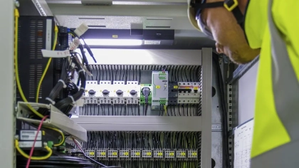
From visual inspections to electrical and mechanical tests, HV switchgear testing ensures safety and reliability. Our recommended diagnostic methods provide clear and reliable condition assessments. High-voltage measurements require strict safety precautions, proper grounding, lockout/tagout procedures, and trained personnel.
Static contact resistance measurement
Static contact resistance measurement
Why Measure it?
In high-voltage switchgear, static contact resistance testing ensures that circuit breaker contacts carry rated current with minimal losses. Rising resistance, caused by surface wear, pressure loss, or oxidation, increases heating and can lead to failure.
How Does it Work?
Static contact resistance is measured using the four-wire method. Two wires inject the test current, while two others measure the voltage drop. This setup enables precise measurements in the micro-ohm range, typically between 10 and 100 μΩ.
Good to Know!
- Insufficient contact pressure can increase resistance.
- The Grounded Contact Resistance (GCR) method allows contact resistance to be measured on both sides of grounded gas-insulated switchgear.


Timing tests
Timing tests
Why Measure it?
High-voltage switching devices control the flow of electrical energy. Grid protection systems can only function correctly if these devices operate within defined parameters. If switching times or sequences deviate from specified limits, this may indicate mechanical or electrical issues within the switchgear. Timing measurements help you detect such deviations early and ensure safe, reliable performance.
How Does it Work?
Switchgear timing testers record opening and closing times, synchronization, and sequence behaviour during operation. Modern timing testers offer a range of functions tailored to different switchgear types and diagnostic needs.
- Main Contact Timing
- Contact Synchronism
- Contact Bounce
- Timing of Auxiliary Contacts
- Timing Test with Integrated Power Supply
- Both-Sides Grounded Timing Test
- Timing Test of Pre-Insertion Resistors
- First Trip Timing Test with Current Clamps


DRM
Dynamic contact resistance measurement
Why Measure it?
A dynamic contact resistance measurement (DRM) reveals wear and condition changes in main and arcing contacts during switching operations. It detects erosion, dimensional changes, and contact damage early, without requiring the circuit breaker to be dismantled.
When DRM is recorded with contact movement, it determines the effective length of current-carrying arcing contacts, enabling precise condition assessment and early failure detection.
How Does it Work?
DRM is a precise four-wire measurement that injects a constant through the contacts while resistance is measured dynamically during switching operations.
Good to Know!
- DRM is widely used on SF₆ circuit breakers to assess arcing contacts, which are often made of tungsten/copper alloy and erode with each interruption.
- The CIBANO 500 performs DRM measurements using the CB MC2 Accessory.
Capacitance and Tan Delta measurements
Capacitance and Tan Delta measurements
Why Measure it?
Capacitance and Tan-Delta measurements reveal the true condition of insulation in high-voltage switchgear. Changes in capacitance can indicate insulation deterioration or damaged grading capacitors. Tracking these values over time helps you plan maintenance, verify repairs, and prevent unexpected downtime.
How Does it Work?
Specialized high-voltage accessories measure capacitance and Tan-Delta. The results are compared with previous measurements, manufacturer specifications, and industry guidelines. Higher Tan-Delta values typically indicate increasing insulation degradation.
Good to Know!
- With low-capacitance equipment such as high-voltage SF₆ circuit breakers, evaluating losses in watts is often more meaningful than using power factor measurements, as outlined in IEEE C57.152.
Motor current measurement
Motor current measurement
Why Measure it?
In high-voltage switchgear, the Motor Current Signature Analysis is a non-intrusive method that evaluates the motor current waveform and runtime to detect deviations from normal behaviour. Analysing inrush and steady-state currents allows you to identify potential mechanical or electrical issues early, helping you optimize maintenance and avoid costly breakdowns or outages.
How Does it Work?
The test measures the current drawn from the motor while the motor charges the spring mechanism or builds up hydraulic or air pressure. Analyzing these currents reveals lubrication issues in the operating mechanism or electrical problems in the drive system.
Good to Know!
- In spring-operated mechanisms, the motor starts immediately after a close operation. The test can be combined with a close timing measurement.
- With independent pole-operated circuit breakers, monitor the motor inrush current carefully.
- Current clamps make testing easy and eliminate the need for rewiring.
Coil current measurement
Coil current measurement
Why Measure it?
In high-voltage circuit breakers, coil current analysis provides valuable insight into critical switching operations. Coil current measurements capture the current signatures of trip and close coils during breaker operation, revealing mechanical and electrical issues such as lubrication problems, latch malfunctions, or unstable control voltage before they turn into real faults.
How Does it Work?
During operation, the current flow in the trip or close coil is recorded and displayed over time. Deviations from the expected curve, including time constant, proportional current, and auxiliary contact timing, indicate electrical or mechanical problems in the operating mechanism.
Good to Know!
- Graphical test result comparisons makes trend analysis fast and effective.
- A stable power source ensures repeatable coil current curves, as voltage variations affect the waveform.
- Advanced test systems combine coil current analysis with timing tests to increase efficiency.
Motion measurement
Motion measurement
Why Measure it?
In high-voltage switchgear, motion measurements are essential when verifying correct operation under high mechanical stress. Motion measurements on high-voltage circuit breakers reveal how well the operating mechanism performs, providing precise data about opening and closing times, contact travel, and speed, ensuring the breaker operates within specified limits.
How Does it Work?
A linear or rotary transducer is attached to the operating mechanism to record movement during operation. Ideally, it should be mounted in the factory test position. If that’s not possible, place it near the main contact and maintain this position for repeatable results.
Good to Know!
- Motion measurements are typically combined with timing or dynamic contact resistance tests.
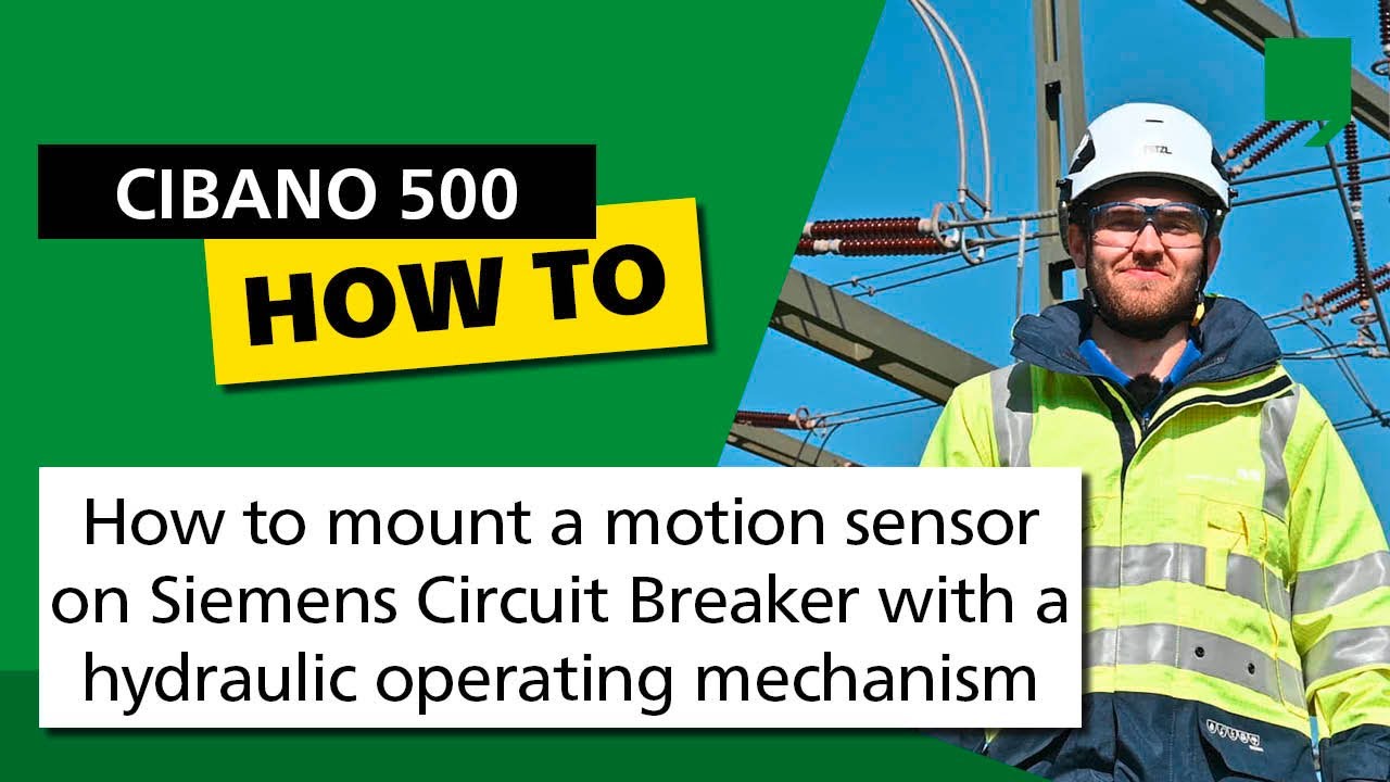
- OMICRON’s YouTube channel offers a wide range of motion sensor mounting videos.
Minimum pick-up test
Minimum pick-up test
Why Measure it?
In high-voltage systems, verifying the minimum pick-up voltage is crucial for reliable operation during varying control conditions. The measurement verifies the lowest voltage at which a circuit breaker reliably trips or closes. It even ensures dependable operation during low-voltage conditions, reducing the risk of equipment damage and arc flash hazards. Confirming proper coil response strengthens system integrity, ensuring safe, reliable performance.
How Does it Work?
Gradually increase the coil’s voltage while monitoring the current. Record the minimum voltage at which the breaker operates, then repeat the test to confirm accuracy and document the results carefully. An unusually high pick-up voltage can indicate issues in the trip coil, control wiring, or related components.
Good to Know!
- Select the test voltage range according to the breaker’s rated voltage and current.
- The exact procedure may vary depending on applicable standards and regulations.
Undervoltage release test
Undervoltage release test
Why Measure it?
In high-voltage applications, undervoltage release testing ensures safe disconnection in critical system conditions. Switchgear without a redundant power supply often uses an undervoltage release to automatically open the circuit breaker when the control voltage drops below a defined level. Testing verifies the exact voltage at which the coil triggers, ensuring reliable protection when the supply voltage fails.
How Does it Work?
First, disconnect and de-energize the system, then apply the control voltage, close the breaker, and gradually reduce the undervoltage coil’s voltage. When the defined threshold is reached and coil trips the breaker, record the trip voltage and any relevant observations.
Good to Know!
- Since this procedure is complex, guided testing increases efficiency and helps prevent errors.
PD
Partial discharge and monitoring
Why Measure it?
Partial Discharge (PD) in high-voltage Gas-Insulated Switchgear (GIS) is a key indicator of insulation deterioration and developing faults. Causes such as floating particles, protrusions, voids, or surface discharges can accelerate aging and lead to serious failures.
How Does it Work?
Online PD monitoring uses specialized sensors to detect and analyse PD signals. The data helps pinpoint the location and severity of defects. It also identifies trends, and triggers alarms if thresholds are exceeded. Results are compared with standards and historical data for assessing insulation health. If PD levels are too high, corrective actions such as repairs or targeted maintenance can be initiated.
Good to Know!
- In tightly sealed SF₆ GIS compartments, built-in UHF sensors are often the most effective solution for reliable PD detection


Static contact resistance measurement
Why Measure it?
In high-voltage switchgear, static contact resistance testing ensures that circuit breaker contacts carry rated current with minimal losses. Rising resistance, caused by surface wear, pressure loss, or oxidation, increases heating and can lead to failure.
How Does it Work?
Static contact resistance is measured using the four-wire method. Two wires inject the test current, while two others measure the voltage drop. This setup enables precise measurements in the micro-ohm range, typically between 10 and 100 μΩ.
Good to Know!
- Insufficient contact pressure can increase resistance.
- The Grounded Contact Resistance (GCR) method allows contact resistance to be measured on both sides of grounded gas-insulated switchgear.
Timing tests
Why Measure it?
High-voltage switching devices control the flow of electrical energy. Grid protection systems can only function correctly if these devices operate within defined parameters. If switching times or sequences deviate from specified limits, this may indicate mechanical or electrical issues within the switchgear. Timing measurements help you detect such deviations early and ensure safe, reliable performance.
How Does it Work?
Switchgear timing testers record opening and closing times, synchronization, and sequence behaviour during operation. Modern timing testers offer a range of functions tailored to different switchgear types and diagnostic needs.
- Main Contact Timing
- Contact Synchronism
- Contact Bounce
- Timing of Auxiliary Contacts
- Timing Test with Integrated Power Supply
- Both-Sides Grounded Timing Test
- Timing Test of Pre-Insertion Resistors
- First Trip Timing Test with Current Clamps
Dynamic contact resistance measurement
Why Measure it?
A dynamic contact resistance measurement (DRM) reveals wear and condition changes in main and arcing contacts during switching operations. It detects erosion, dimensional changes, and contact damage early, without requiring the circuit breaker to be dismantled.
When DRM is recorded with contact movement, it determines the effective length of current-carrying arcing contacts, enabling precise condition assessment and early failure detection.
How Does it Work?
DRM is a precise four-wire measurement that injects a constant through the contacts while resistance is measured dynamically during switching operations.
Good to Know!
- DRM is widely used on SF₆ circuit breakers to assess arcing contacts, which are often made of tungsten/copper alloy and erode with each interruption.
- The CIBANO 500 performs DRM measurements using the CB MC2 Accessory.
Capacitance and Tan Delta measurements
Why Measure it?
Capacitance and Tan-Delta measurements reveal the true condition of insulation in high-voltage switchgear. Changes in capacitance can indicate insulation deterioration or damaged grading capacitors. Tracking these values over time helps you plan maintenance, verify repairs, and prevent unexpected downtime.
How Does it Work?
Specialized high-voltage accessories measure capacitance and Tan-Delta. The results are compared with previous measurements, manufacturer specifications, and industry guidelines. Higher Tan-Delta values typically indicate increasing insulation degradation.
Good to Know!
- With low-capacitance equipment such as high-voltage SF₆ circuit breakers, evaluating losses in watts is often more meaningful than using power factor measurements, as outlined in IEEE C57.152.
Motor current measurement
Why Measure it?
In high-voltage switchgear, the Motor Current Signature Analysis is a non-intrusive method that evaluates the motor current waveform and runtime to detect deviations from normal behaviour. Analysing inrush and steady-state currents allows you to identify potential mechanical or electrical issues early, helping you optimize maintenance and avoid costly breakdowns or outages.
How Does it Work?
The test measures the current drawn from the motor while the motor charges the spring mechanism or builds up hydraulic or air pressure. Analyzing these currents reveals lubrication issues in the operating mechanism or electrical problems in the drive system.
Good to Know!
- In spring-operated mechanisms, the motor starts immediately after a close operation. The test can be combined with a close timing measurement.
- With independent pole-operated circuit breakers, monitor the motor inrush current carefully.
- Current clamps make testing easy and eliminate the need for rewiring.
Coil current measurement
Why Measure it?
In high-voltage circuit breakers, coil current analysis provides valuable insight into critical switching operations. Coil current measurements capture the current signatures of trip and close coils during breaker operation, revealing mechanical and electrical issues such as lubrication problems, latch malfunctions, or unstable control voltage before they turn into real faults.
How Does it Work?
During operation, the current flow in the trip or close coil is recorded and displayed over time. Deviations from the expected curve, including time constant, proportional current, and auxiliary contact timing, indicate electrical or mechanical problems in the operating mechanism.
Good to Know!
- Graphical test result comparisons makes trend analysis fast and effective.
- A stable power source ensures repeatable coil current curves, as voltage variations affect the waveform.
- Advanced test systems combine coil current analysis with timing tests to increase efficiency.
Motion measurement
Why Measure it?
In high-voltage switchgear, motion measurements are essential when verifying correct operation under high mechanical stress. Motion measurements on high-voltage circuit breakers reveal how well the operating mechanism performs, providing precise data about opening and closing times, contact travel, and speed, ensuring the breaker operates within specified limits.
How Does it Work?
A linear or rotary transducer is attached to the operating mechanism to record movement during operation. Ideally, it should be mounted in the factory test position. If that’s not possible, place it near the main contact and maintain this position for repeatable results.
Good to Know!
- Motion measurements are typically combined with timing or dynamic contact resistance tests.
- OMICRON’s YouTube channel offers a wide range of motion sensor mounting videos.
Minimum pick-up test
Why Measure it?
In high-voltage systems, verifying the minimum pick-up voltage is crucial for reliable operation during varying control conditions. The measurement verifies the lowest voltage at which a circuit breaker reliably trips or closes. It even ensures dependable operation during low-voltage conditions, reducing the risk of equipment damage and arc flash hazards. Confirming proper coil response strengthens system integrity, ensuring safe, reliable performance.
How Does it Work?
Gradually increase the coil’s voltage while monitoring the current. Record the minimum voltage at which the breaker operates, then repeat the test to confirm accuracy and document the results carefully. An unusually high pick-up voltage can indicate issues in the trip coil, control wiring, or related components.
Good to Know!
- Select the test voltage range according to the breaker’s rated voltage and current.
- The exact procedure may vary depending on applicable standards and regulations.
Undervoltage release test
Why Measure it?
In high-voltage applications, undervoltage release testing ensures safe disconnection in critical system conditions. Switchgear without a redundant power supply often uses an undervoltage release to automatically open the circuit breaker when the control voltage drops below a defined level. Testing verifies the exact voltage at which the coil triggers, ensuring reliable protection when the supply voltage fails.
How Does it Work?
First, disconnect and de-energize the system, then apply the control voltage, close the breaker, and gradually reduce the undervoltage coil’s voltage. When the defined threshold is reached and coil trips the breaker, record the trip voltage and any relevant observations.
Good to Know!
- Since this procedure is complex, guided testing increases efficiency and helps prevent errors.
Partial discharge and monitoring
Why Measure it?
Partial Discharge (PD) in high-voltage Gas-Insulated Switchgear (GIS) is a key indicator of insulation deterioration and developing faults. Causes such as floating particles, protrusions, voids, or surface discharges can accelerate aging and lead to serious failures.
How Does it Work?
Online PD monitoring uses specialized sensors to detect and analyse PD signals. The data helps pinpoint the location and severity of defects. It also identifies trends, and triggers alarms if thresholds are exceeded. Results are compared with standards and historical data for assessing insulation health. If PD levels are too high, corrective actions such as repairs or targeted maintenance can be initiated.
Good to Know!
- In tightly sealed SF₆ GIS compartments, built-in UHF sensors are often the most effective solution for reliable PD detection
Recommended solutions
Find The Right Solution for Your Application
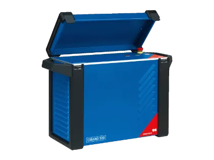
HV Circuit Breaker Testing with our expert CIBANO 500
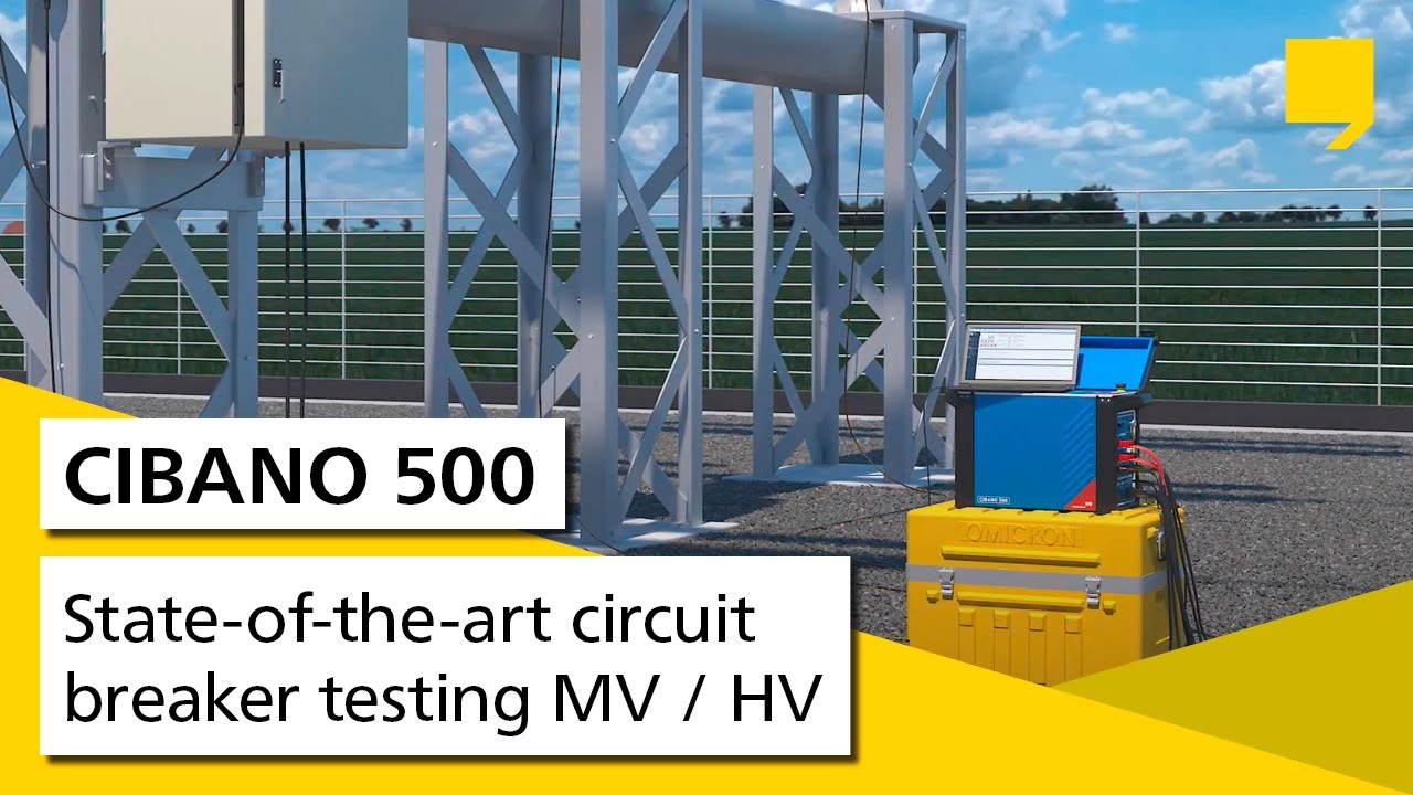
CIBANO 500 is our dedicated circuit breaker test device and provides guided assistance to ensure a seamless workflow.
- Static contact resistance measurement up to 200 A DC
- Timing Tests
- Dynamic contact resistance measurement
- Motor current measurement
- Coil current measurement
- Motion measurement
- Minimum pick-up test
- Undervoltage release test
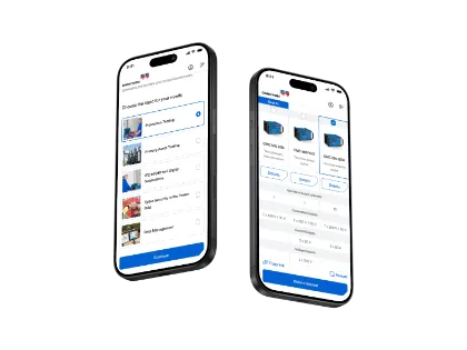
- Guided Workflow with Primary Test Manager
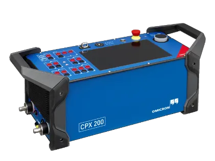
HV Switchgear Testing with the talented, multifunctional CPX 200
Powerful, compact and lightweight, our new primary asset test device, CPX 200, is ready to support your daily testing routine.
- Static contact resistance measurement up to 1 000 A DC
- Timing Tests
- Capacitance and Tan Delta measurements
- Motor current measurement
- Coil current measurement
- Guided Workflows with CPXpert Software and TouchControl
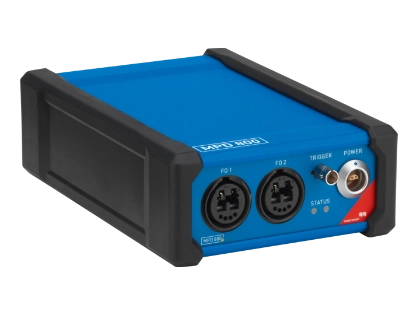
HV GIS Testing and Monitoring with MPD 800
MPD 800 is a portable universal multichannel PD measuring system, great for detecting early deviations.
- In accordance with IEC 60270
- High Frequency Current Transformer (HFCT)
HV GIS Testing and Monitoring
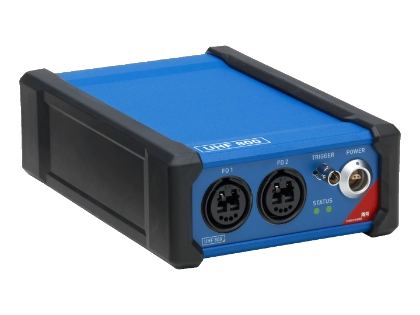
UHF 800 is our dedicated UHF PD measuring system.
- Ultra-High Frequency (UHF)
HV GIS Testing and Monitoring with PARADIMO 100
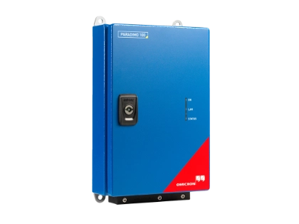
PARADIMO 100 is designed for continuous PD monitoring and trending.
- Ultra-High Frequency (UHF)
HV Circuit Breaker Testing with COMPANO 100
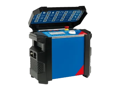
COMPANO 100 is a lightweight, battery-powered multi-purpose test device ready to support your switchgear testing.
- Static contact resistance measurement up to 100 A DC
- Timing Tests
- Motor current measurement
HV Circuit Breaker Testing with CMC 500
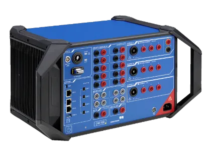
CMC 500 is a modular, multi-phase protection relay test set and commissioning tool offering a variety of SG testing.
- Timing Tests
- Motor current measurement
- Coil current measurement
- Minimum pick-up test
- Undervoltage release test
Elevate your testing workflow with solutions designed to save time, maximize safety, and extract the highest value from your results. CIBANO 500 serves as your expert, while your multifunctional companion for a wide range of switching devices, the CPX 200, streamlines your daily routines. MPD 800, UHF 800, and PARADIMO 100 deliver deep insights into advanced GIS monitoring.
Andreas Nenning
Product Manager
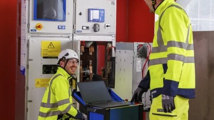
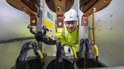
Built to Protect: Medium-Voltage Switchgear Reliability
Switchgear assets are the foundation of a stable and dependable power network. Applying proactive service strategies and preventive maintenance enables you to control the impact of environmental conditions, aging components, and operational stress. This reduces interruptions, prevents large-scale failures, and secures sustainable system reliability and performance.
Testing Methods
Medium Voltage Switchgear Diagnostic Tests
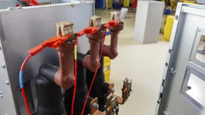
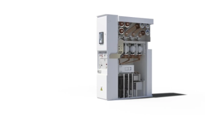
From visual inspections to electrical and mechanical tests, MV switchgear testing ensures safety and reliability. Our recommended diagnostic methods provide a clear, reliable condition assessment for various medium-voltage circuit breaker components.
Static contact resistance measurement
Static contact resistance measurement
Why Measure it?
In medium-voltage switchgear, contact resistance measurements support stable operation and helps prevent localized overheating. Static contact resistance testing ensures that circuit breaker contacts carry rated current with minimal losses. Rising resistance, caused by surface wear, pressure loss, or oxidation, increases heating and can lead to failure.
How Does it Work?
Static contact resistance is measured using the four-wire method. Two wires inject the test current, while two others measure the voltage drop. This setup enables precise measurements in the micro-ohm range, typically between 10 and 100 μΩ.
Good to Know!
- Insufficient contact pressure can increase resistance.
- Higher injection currents, up to the nominal current, can be beneficial on-air insulated switches to overcome oxidation.
Timing tests
Timing tests
Why Measure it?
High-voltage switching devices control the flow of electrical energy. Grid protection systems can only function correctly if these devices operate within defined parameters. If switching times or sequences deviate from specified limits, this may indicate mechanical or electrical issues within the switchgear. Timing measurements help you detect such deviations early and ensure safe, reliable performance.
How Does it Work?
Switchgear timing testers record opening and closing times, synchronization, and sequence behaviour during operation. Modern timing testers offer a range of functions tailored to different switchgear types and diagnostic needs.
- Main Contact Timing
- Contact Synchronism
- Contact Bounce
- Timing of Auxiliary Contacts
- Timing Test with Integrated Power Supply
- With VDS (Voltage Detection System)
- In-Service Testing with Current Clamps
Coil current measurement
Coil current measurement
Why Measure it?
In medium-voltage switchgear, coil current measurements support routine diagnostics and reliable operation. The measurements capture the current signatures of trip and close coils during breaker operation, revealing mechanical and electrical issues such as lubrication problems, latch malfunctions, or unstable control voltage before they turn into real faults.
How Does it Work?
During operation, the current flow in the trip or close coil is recorded and displayed over time. Deviations from the expected curve, including time constant, proportional current, and auxiliary contact timing, indicate electrical or mechanical problems in the operating mechanism.
Good to Know!
- Graphical comparison test result comparisons makes trend analysis fast and effective.
- A stable power source ensures repeatable coil current curves, as voltage variations affect the waveform.
- Advanced test systems combine coil current analysis with timing tests to increase efficiency.
Motor current measurement
Motor current measurement
Why Measure it?
In medium-voltage switchgear, motor current measurements help identify mechanical wear during regular operation. Motor Current Signature Analysis is a non-intrusive method that evaluates the motor current waveform and runtime to detect deviations from normal behavior. Analyzing inrush and steady-state currents allows you to identify potential mechanical or electrical issues early, helping you optimize maintenance and avoid costly breakdowns or outages.
How Does it Work?
The test measures the current drawn from the motor while the motor charges the spring mechanism. Analyzing the current curve reveals lubrication issues or electrical problems in the drive system.
Good to Know!
- Use a precise, adjustable power supply for accurate fingerprint comparisons at minimum, nominal, and maximum voltage.
- Combine the test with a close timing measurement, as the motor starts immediately after closing.
- Current clamps simplify testing and eliminate the need for rewiring.
Motion measurement
Motion measurement
Why Measure it?
In medium-voltage switchgear, motion measurements ensure proper mechanical performance during typical service conditions. Motion measurements on medium-voltage circuit breakers reveal how well the operating mechanism performs, providing precise data about opening and closing times, contact travel, and speed, ensuring the breaker operates within specified limits.
How Does it Work?
A linear or rotary transducer is attached to the operating mechanism to record movement during operation. Ideally, it should be mounted in the factory test position. If that’s not possible, place it near the main contact and maintain this position for repeatable results.
Good to Know!
- Motion measurements are typically combined with timing measurements.
- OMICRON’s YouTube channel offers a wide range of motion sensor mounting videos.
Minimum pick-up test
Minimum pick-up test
Why Measure it?
In medium-voltage systems, the minimum pick-up test ensures dependable operation in standard grid environments. The test verifies the lowest voltage at which a circuit breaker reliably trips or closes. It even ensures dependable operation even under low-voltage conditions, reducing the risk of equipment damage and arc flash hazards. Confirming proper coil response strengthens system integrity, ensuring safe, reliable performance.
How Does it Work?
Gradually increase the coil’s voltage while monitoring the current. Record the minimum voltage at which the breaker operates, then repeat the test to confirm accuracy and document the results carefully. An unusually high pick-up voltage can indicate issues in the trip coil, control wiring, or related components.
Good to Know!
- Select the test voltage range according to the breaker’s rated voltage.
- The exact procedure may vary depending on applicable standards and regulations.
Undervoltage release test
Undervoltage release test
Why Measure it?
In medium-voltage systems, undervoltage release testing supports reliable protection in distribution networks. Switchgear without a redundant power supply often uses an undervoltage release to automatically open the circuit breaker when the control voltage drops below a defined level. Testing verifies the exact voltage at which the coil triggers, ensuring reliable protection when the supply voltage fails.
How Does it Work?
First, disconnect and de-energize the system, then apply the control voltage, close the breaker, and gradually reduce the undervoltage coil’s voltage. When the defined threshold is reached and the coil trips the breaker, record the trip voltage and any relevant observations.
Good to Know!
- Since this procedure is complex, guided testing increases efficiency and helps prevent errors.
Over current release test
Over current release test
Why Measure it?
Overcurrent releases protection breakers in substations without auxiliary supply voltage. They’re triggered by current from a tripping transformer, typically 0.5, 1, or 5 A AC, via a self-powered overcurrent protection relay. If a fault occurs, the breaker will open and isolate the affected grid section.
How Does it Work?
The overcurrent release test determines the current level at which the breaker trips, providing key insights into release performance.
Good to Know!
- The CIBANO 500 Medium Voltage Package includes guided under-voltage and overcurrent release tests, using its integrated supply to generate voltage or current ramps.
Delay time measurement
Delay time measurement
Why Measure it?
Modern substations rely on digital communication links to exchange measurement data and control commands. During commissioning, verifying the correct configuration and installation is crucial for ensuring reliable operation.
How Does it Work?
Delay time measurements evaluate the interval between an IEC 61850 trip command (goose) and the actual opening of the primary circuit contacts. The results are compared with manufacturer specifications or coordination requirements, and any deviations are documented.
Good to Know!
- Plan testing during the smart substation design phase and include dedicated test ports for network switches.
PD
Partial discharge measurement
Why Measure it?
Partial discharge (PD) indicates insulation defects such as voids or weak spots that can lead to premature failure in MV switchgear. PD measurement helps detect and locate these issues early, allowing you to adjust maintenance plans and prevent costly downtime.
How Does it Work?
PD measurements can be performed offline with an applied test voltage or online using installed sensors without disconnecting the asset. The system detects and quantifies discharge signals to assess insulation condition and identify potential defects.
- Measurement according to IEC 60270
- Voltage Detection System (VDS) detection
- Cable termination detection
- Transient Earth Voltage (TEV) detection
Good to Know!
- PD measurements on MV switchgear help assess insulation quality and detect potential issues.
- Accurate results require expert knowledge and specialized equipment.
Static contact resistance measurement
Why Measure it?
In medium-voltage switchgear, contact resistance measurements support stable operation and helps prevent localized overheating. Static contact resistance testing ensures that circuit breaker contacts carry rated current with minimal losses. Rising resistance, caused by surface wear, pressure loss, or oxidation, increases heating and can lead to failure.
How Does it Work?
Static contact resistance is measured using the four-wire method. Two wires inject the test current, while two others measure the voltage drop. This setup enables precise measurements in the micro-ohm range, typically between 10 and 100 μΩ.
Good to Know!
- Insufficient contact pressure can increase resistance.
- Higher injection currents, up to the nominal current, can be beneficial on-air insulated switches to overcome oxidation.
Timing tests
Why Measure it?
High-voltage switching devices control the flow of electrical energy. Grid protection systems can only function correctly if these devices operate within defined parameters. If switching times or sequences deviate from specified limits, this may indicate mechanical or electrical issues within the switchgear. Timing measurements help you detect such deviations early and ensure safe, reliable performance.
How Does it Work?
Switchgear timing testers record opening and closing times, synchronization, and sequence behaviour during operation. Modern timing testers offer a range of functions tailored to different switchgear types and diagnostic needs.
- Main Contact Timing
- Contact Synchronism
- Contact Bounce
- Timing of Auxiliary Contacts
- Timing Test with Integrated Power Supply
- With VDS (Voltage Detection System)
- In-Service Testing with Current Clamps
Coil current measurement
Why Measure it?
In medium-voltage switchgear, coil current measurements support routine diagnostics and reliable operation. The measurements capture the current signatures of trip and close coils during breaker operation, revealing mechanical and electrical issues such as lubrication problems, latch malfunctions, or unstable control voltage before they turn into real faults.
How Does it Work?
During operation, the current flow in the trip or close coil is recorded and displayed over time. Deviations from the expected curve, including time constant, proportional current, and auxiliary contact timing, indicate electrical or mechanical problems in the operating mechanism.
Good to Know!
- Graphical comparison test result comparisons makes trend analysis fast and effective.
- A stable power source ensures repeatable coil current curves, as voltage variations affect the waveform.
- Advanced test systems combine coil current analysis with timing tests to increase efficiency.
Motor current measurement
Why Measure it?
In medium-voltage switchgear, motor current measurements help identify mechanical wear during regular operation. Motor Current Signature Analysis is a non-intrusive method that evaluates the motor current waveform and runtime to detect deviations from normal behavior. Analyzing inrush and steady-state currents allows you to identify potential mechanical or electrical issues early, helping you optimize maintenance and avoid costly breakdowns or outages.
How Does it Work?
The test measures the current drawn from the motor while the motor charges the spring mechanism. Analyzing the current curve reveals lubrication issues or electrical problems in the drive system.
Good to Know!
- Use a precise, adjustable power supply for accurate fingerprint comparisons at minimum, nominal, and maximum voltage.
- Combine the test with a close timing measurement, as the motor starts immediately after closing.
- Current clamps simplify testing and eliminate the need for rewiring.
Motion measurement
Why Measure it?
In medium-voltage switchgear, motion measurements ensure proper mechanical performance during typical service conditions. Motion measurements on medium-voltage circuit breakers reveal how well the operating mechanism performs, providing precise data about opening and closing times, contact travel, and speed, ensuring the breaker operates within specified limits.
How Does it Work?
A linear or rotary transducer is attached to the operating mechanism to record movement during operation. Ideally, it should be mounted in the factory test position. If that’s not possible, place it near the main contact and maintain this position for repeatable results.
Good to Know!
- Motion measurements are typically combined with timing measurements.
- OMICRON’s YouTube channel offers a wide range of motion sensor mounting videos.
Minimum pick-up test
Why Measure it?
In medium-voltage systems, the minimum pick-up test ensures dependable operation in standard grid environments. The test verifies the lowest voltage at which a circuit breaker reliably trips or closes. It even ensures dependable operation even under low-voltage conditions, reducing the risk of equipment damage and arc flash hazards. Confirming proper coil response strengthens system integrity, ensuring safe, reliable performance.
How Does it Work?
Gradually increase the coil’s voltage while monitoring the current. Record the minimum voltage at which the breaker operates, then repeat the test to confirm accuracy and document the results carefully. An unusually high pick-up voltage can indicate issues in the trip coil, control wiring, or related components.
Good to Know!
- Select the test voltage range according to the breaker’s rated voltage.
- The exact procedure may vary depending on applicable standards and regulations.
Undervoltage release test
Why Measure it?
In medium-voltage systems, undervoltage release testing supports reliable protection in distribution networks. Switchgear without a redundant power supply often uses an undervoltage release to automatically open the circuit breaker when the control voltage drops below a defined level. Testing verifies the exact voltage at which the coil triggers, ensuring reliable protection when the supply voltage fails.
How Does it Work?
First, disconnect and de-energize the system, then apply the control voltage, close the breaker, and gradually reduce the undervoltage coil’s voltage. When the defined threshold is reached and the coil trips the breaker, record the trip voltage and any relevant observations.
Good to Know!
- Since this procedure is complex, guided testing increases efficiency and helps prevent errors.
Over current release test
Why Measure it?
Overcurrent releases protection breakers in substations without auxiliary supply voltage. They’re triggered by current from a tripping transformer, typically 0.5, 1, or 5 A AC, via a self-powered overcurrent protection relay. If a fault occurs, the breaker will open and isolate the affected grid section.
How Does it Work?
The overcurrent release test determines the current level at which the breaker trips, providing key insights into release performance.
Good to Know!
- The CIBANO 500 Medium Voltage Package includes guided under-voltage and overcurrent release tests, using its integrated supply to generate voltage or current ramps.
Delay time measurement
Why Measure it?
Modern substations rely on digital communication links to exchange measurement data and control commands. During commissioning, verifying the correct configuration and installation is crucial for ensuring reliable operation.
How Does it Work?
Delay time measurements evaluate the interval between an IEC 61850 trip command (goose) and the actual opening of the primary circuit contacts. The results are compared with manufacturer specifications or coordination requirements, and any deviations are documented.
Good to Know!
- Plan testing during the smart substation design phase and include dedicated test ports for network switches.
Partial discharge measurement
Why Measure it?
Partial discharge (PD) indicates insulation defects such as voids or weak spots that can lead to premature failure in MV switchgear. PD measurement helps detect and locate these issues early, allowing you to adjust maintenance plans and prevent costly downtime.
How Does it Work?
PD measurements can be performed offline with an applied test voltage or online using installed sensors without disconnecting the asset. The system detects and quantifies discharge signals to assess insulation condition and identify potential defects.
- Measurement according to IEC 60270
- Voltage Detection System (VDS) detection
- Cable termination detection
- Transient Earth Voltage (TEV) detection
Good to Know!
- PD measurements on MV switchgear help assess insulation quality and detect potential issues.
- Accurate results require expert knowledge and specialized equipment.
Find The Right Solution for Your Application
MV Circuit Breaker Testing with our expert CIBANO 500
CIBANO 500 is our dedicated circuit breaker testing device, providing guided assistance for a seamless workflow.
- Static contact resistance measurement up to 200 A DC
- Timing Tests
- Coil current measurement
- Motor current measurement
- Motion measurement
- Minimum pick-up test
- Undervoltage release test
- Overcurrent release test
- Guided Workflow with Primary Test Manager
MV Switchgear Testing with our talented, multifunctional CPX 200
Powerful, compact and lightweight, our new primary asset CPX 200 testing device is ready to support your daily testing routine.
- Static contact resistance measurement up to 1 000 A DC
- Timing Tests
- Coil current measurement
- Motor current measurement
- Guided Workflows with CPXpert Sofware and TouchControl
MV Switchgear Testing and Monitoring with MPD 800
The MPD 800 is a portable universal multichannel PD measuring system, great for detecting early deviations.
- In accordance with IEC 60270
- Transient Earth Voltage (TEV)
- High Frequency Current Transformer (HFCT)
- Voltage Detection System (VDS)
MV Switchgear Testing with COMPANO 100
The COMPANO 100 is a lightweight, battery powered multi-purpose testing device that supports switchgear testing.
- Static contact resistance measurement up to 100 A DC
- Timing Tests
- Motor current measurement
MV Switchgear Testing with CMC 500
CMC 500 is a modular, multi-phase protection relay test set and commissioning tool, providing a wide range of SG tests.
- Timing Tests
- Coil current measurement
- Motor current measurement
- Minimum pick-up test
- Undervoltage release test
- Overcurrent release test
- Delay time measurement
Boost your efficiency, enhance safety, and unlock the full value of your test results with our powerful solutions. CIBANO 500 delivers specialized expertise, while CPX 200 ensures speed and flexibility. The MPD 800 provides essential, reliable diagnostic capabilities for condition assessments of MV switchgear.
Andreas Nenning
Product Manager
Related Products
Insights

Related Videos




Which devices does OMICRON offer for testing LV, MV or HV circuit breakers?
- For the circuit breaker specialists, we offer the CIBANO 500.
- For general primary asset testing we suggest the CPX 200.
- For partial discharge testing, our MPD 800 is for the specialists and PARADIMO 100 is for HV GIS continuous monitoring.
- For combining switching device tests with protection relay tests, we suggest using the CMC 500 for advanced testing and the COMPANO 100 for basic testing.
Is it possible to test GIS with both sides grounded using OMICRON equipment?
The CIBANO 500 provides the Current Sensor Method (CSM) for timing and the Grounded Contact Resistance (GCR) method for contact resistance measurements on GIS with both sides grounded.
Does OMICRON offer adapters for measuring circuit breaker motion?
We provide rotary adapters for generic linear motion measurements with different lengths.
Which breakers/operating mechanisms does OMICRON provide motion sensors for?
We provide adapters for the following types of circuit breakers:
- Siemens SPS/3AP up to 145 kV and 3AP > 145 kV, Linear transducer for graphite nozzle breakers
- ABB HPL/LTB > 145 kV, HMB 4/8 operating mechanism
- Alstom/GE: GL > 72.5 kV, HYpact
Does OMICRON have any references for mounting motion sensors on specific breaker types?
On our YouTube channel we provide a wide selection of motion sensor mounting videos.
Which measurements can be performed on switchgear with OMICRON equipment?
Diagnostic Tests:
- Contact Resistance
- Timing tests
- Dynamic contact resistance
- capacitance and tan delta measurements
- motor current measurements
- coil current measurements
- motion measurements
- minimum pick-up test
- undervoltage release test
- overcurrent release test
- delay time measurement
Monitoring:
- Partial discharge (PD) according to IEC 60270
- Ultra-High Frequency (UHF) PD monitoring
- High Frequency Current Transformer (HFCT) PD testing
- PD via Voltage Detection System (VTS)
- Transient Earth Voltage (TEV) PD measurements
Is it necessary to perform motion measurements on MV circuit breakers?
It’s recommended for circuit breakers when mechanical linkage is exposed to harsh environments, or in critical positions within the electrical grid.
How often do I have to perform circuit breaker measurements?
Factory Acceptance Tests and Site Commissioning Tests are conducted anywhere from once a year to never, depending on their maintenance strategy.
How can I enhance the results from contact resistance measurements?
Under certain conditions, increasing the test current can improve the accuracy of contact resistance measurements. Such conditions can include contact oxidation from environmental exposure.
Looking for some guidance on this topic?