Power Transformers
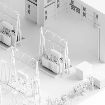
Ensuring Reliable Power Transformer Operation
During commissioning and operation, your power transformer must be in good condition. Many factors can affect your transformer's expected lifetime throughout its lifecycle.
Diagnostic testing and transformer monitoring systems provide actionable insights into insulation condition, winding integrity, tap changer performance, and partial discharge activity.
By combining offline transformer testing with online partial discharge monitoring and advanced dielectric diagnostics, you can identify risks early, plan maintenance strategically, and extend asset service life.
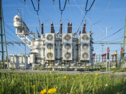
Managing Transformer Aging and Risk
Moisture
Moisture in solid insulation can result from paper aging, leakage through transformer seals, or breathing. It leads to reduced breakdown strength and faster insulation aging.
Knowing the moisture content enables you to perform condition-based maintenance, reducing failures and avoiding unnecessary replacements.
Mechanical influences
Short circuit forces, seismic events, or transport damage can deform windings and core components. Non-invasive methods such as sweep frequency response analysis (SFRA) and short circuit impedance measurements, detect these defects early, ensuring safety and reliability.
Partial Discharge Activity
Partial discharge (PD) in bushings or windings indicates insulation defects long before a breakdown occurs. Our testing systems enable you to detect partial discharges at an early stage and determine their source locations acoustically.
OLTC wear and contact issues
On-load tap changers (OLTCs) are electrically and mechanically stressed components. Static and dynamic resistance measurements (DRM) and vibro-acoustic measurements (VAM) help you perform a reliable condition assessment.
Comprehensive Transformer Diagnostics
Power transformer condition assessments combine electrical, dielectric, and mechanical diagnostic measurements throughout your transformer’s lifecycle, from factory acceptance testing to commissioning and service.
3
True three-phase testing without rewiring
66%
of testing time with TESTRANO 600
19
2
hours with DIRANA
10
uHz
20
MPD 800 units and UHF 800
Power Transformer Measurement Methods
Capacitance and power factor measurement
Capacitance and power factor/dissipation factor measurement
Capacitance and power factor (tan δ) measurements evaluate the condition of insulation in windings and bushings. They quantify dielectric losses and help you assess insulation performance.
An increased dissipation factor indicates moisture ingress, aging, contamination, or partial breakdown between capacitive layers. Detecting these trends early can prevent bushing failure and reduce the risk of outages. The results also support condition-based maintenance and compliance with International Electrotechnical Commission (IEC) and Institute of Electrical and Electronics Engineers (IEEE) limits.


Insulation resistance measurement
Insulation resistance measurement
Insulation resistance tests detect moisture, contamination, and deterioration in transformer insulation before breakdown occurs. By trending the resistance values, polarization index (PI), and the dielectric absorption ratio (DAR), you can identify aging effects or leakage paths that increase the risk of failure.
Regular testing supports your maintenance planning and extends the service life of your assets. It also reduces unplanned downtime by revealing insulation weaknesses early.
Winding resistance measurement
Winding resistance measurement
Winding resistance measurements verify the integrity of conductors, helping you identify contact problems, open circuits, and high-resistance connections in windings and on-load tap changer (OLTC) paths.
Deviations between phases or tap positions indicate a risk of overheating or mechanical issues. The test helps you validate factory data and supports tap changer diagnostics, ensuring reliable current distribution under load.
OLTC Scan
Dynamic resistance measurement resp. OLTC Scan
Dynamic resistance measurements evaluate how an on-load tap changer (OLTC) switches during operation by capturing the transient current during its movement.
It reveals contact wear, timing deviations, and interruptions that static tests cannot detect. Identifying switching irregularities early enables predictive maintenance planning, preventing severe OLTC failures.
VAM
Vibro-acoustic measurement
Vibro-acoustic measurements assess the mechanical condition of an on-load tap changer (OLTC). This method analyzes vibration signals that occur during switching.
Changes in the acoustic pattern indicate contact wear, mechanical misalignment, or drive issues. You can perform this test online without shutting down the transformer. Detecting mechanical degradation early helps you increase reliability and plan effective maintenance activities.
TTR measurement
Transformer turns ratio (TTR) measurement
Transformer turns ratio tests verify the accuracy of the ratio and the phase displacement between windings by detecting shorted turns, open circuits, and incorrect tap positions. These issues can affect voltage regulation and protection coordination.
Comparing results with nameplate data ensures compliance with International Electrotechnical Commission (IEC) and Institute of Electrical and Electronics Engineers (IEEE) standards. This test also confirms that a transformer is operating correctly.
Exciting current measurement
Exciting current measurement
Exciting current measurements evaluate insulation between turns, the magnetic core's condition, and the tap changer's integrity during no-load conditions.
Phase deviations or abnormal patterns indicate shorted turns, core damage, or wiring issues. The test provides a quick insight into the condition of the magnetic circuit and complements transformer turns ratio (TTR) and winding resistance diagnostics.
Short-circuit impedance / leakage reactance measurement
Short-circuit impedance / leakage reactance measurement
Short-circuit impedance tests detect winding deformations that may have resulted from fault currents or transport stress.
Variations from nameplate impedance values indicate mechanical displacement and can reduce dielectric strength.
This measurement helps you safeguard transformer stability and verify the unit's structural integrity before returning it to service.
Capacitance and power factor/dissipation factor measurement
Capacitance and power factor (tan δ) measurements evaluate the condition of insulation in windings and bushings. They quantify dielectric losses and help you assess insulation performance.
An increased dissipation factor indicates moisture ingress, aging, contamination, or partial breakdown between capacitive layers. Detecting these trends early can prevent bushing failure and reduce the risk of outages. The results also support condition-based maintenance and compliance with International Electrotechnical Commission (IEC) and Institute of Electrical and Electronics Engineers (IEEE) limits.
Insulation resistance measurement
Insulation resistance tests detect moisture, contamination, and deterioration in transformer insulation before breakdown occurs. By trending the resistance values, polarization index (PI), and the dielectric absorption ratio (DAR), you can identify aging effects or leakage paths that increase the risk of failure.
Regular testing supports your maintenance planning and extends the service life of your assets. It also reduces unplanned downtime by revealing insulation weaknesses early.
Winding resistance measurement
Winding resistance measurements verify the integrity of conductors, helping you identify contact problems, open circuits, and high-resistance connections in windings and on-load tap changer (OLTC) paths.
Deviations between phases or tap positions indicate a risk of overheating or mechanical issues. The test helps you validate factory data and supports tap changer diagnostics, ensuring reliable current distribution under load.
Dynamic resistance measurement resp. OLTC Scan
Dynamic resistance measurements evaluate how an on-load tap changer (OLTC) switches during operation by capturing the transient current during its movement.
It reveals contact wear, timing deviations, and interruptions that static tests cannot detect. Identifying switching irregularities early enables predictive maintenance planning, preventing severe OLTC failures.
Vibro-acoustic measurement
Vibro-acoustic measurements assess the mechanical condition of an on-load tap changer (OLTC). This method analyzes vibration signals that occur during switching.
Changes in the acoustic pattern indicate contact wear, mechanical misalignment, or drive issues. You can perform this test online without shutting down the transformer. Detecting mechanical degradation early helps you increase reliability and plan effective maintenance activities.
Transformer turns ratio (TTR) measurement
Transformer turns ratio tests verify the accuracy of the ratio and the phase displacement between windings by detecting shorted turns, open circuits, and incorrect tap positions. These issues can affect voltage regulation and protection coordination.
Comparing results with nameplate data ensures compliance with International Electrotechnical Commission (IEC) and Institute of Electrical and Electronics Engineers (IEEE) standards. This test also confirms that a transformer is operating correctly.
Exciting current measurement
Exciting current measurements evaluate insulation between turns, the magnetic core's condition, and the tap changer's integrity during no-load conditions.
Phase deviations or abnormal patterns indicate shorted turns, core damage, or wiring issues. The test provides a quick insight into the condition of the magnetic circuit and complements transformer turns ratio (TTR) and winding resistance diagnostics.
Short-circuit impedance / leakage reactance measurement
Short-circuit impedance tests detect winding deformations that may have resulted from fault currents or transport stress.
Variations from nameplate impedance values indicate mechanical displacement and can reduce dielectric strength.
This measurement helps you safeguard transformer stability and verify the unit's structural integrity before returning it to service.
FRSL
Frequency response from stray losses (FRSL) measurement
The frequency response from stray losses (FRSL) measurement helps you identify strand-to-strand short circuits and local overheating. This method analyzes the short-circuit impedance's resistive component across a range of frequencies.
An increase in stray losses at higher frequencies reveals faults in parallel conductors. This test provides advanced diagnostics, going beyond conventional impedance measurements.
Demagnetization
Demagnetization
Demagnetization removes residual magnetism from the transformer core after testing direct current (DC) or isolation. Residual flux can cause high inrush currents and distort diagnostic results later.
Controlled demagnetization helps protect personnel and equipment during energization, ensuring accurate exciting current and sweep frequency response analysis (SFRA) measurements.
DFR
Dielectric frequency response analysis
Dielectric frequency response (DFR) analysis determines moisture content in cellulose insulation and evaluates oil conductivity. Moisture accelerates aging and reduces dielectric strength.
This method models the dissipation factor over a wide frequency range, providing a reliable, non-invasive assessment of insulation condition. The results can be used to support service life management decisions.
SFRA
Sweep frequency response analysis (SFRA)
Sweep frequency response analysis (SFRA) detects mechanical movement, winding deformation, and core displacement. This method compares a transformer’s frequency response with reference data.
Even small shifts in resonance indicate structural changes after faults or transport, and this test provides a highly sensitive mechanical integrity assessment without applying high voltage.

Bushing CT analysis
Bushing current transformer (CT) analysis
Bushing current transformer (CT) analysis verifies the accuracy of the ratio, phase displacement, excitation behavior, and protection class.
Incorrect CT performance can cause protection maloperation and asset damage. Testing the bushing CT ensures compliance with the International Electrotechnical Commission (IEC) and Institute of Electrical and Electronics Engineers (IEEE) standards, ensuring reliable signal transmission for protection systems.

PD analysis
Partial discharge analysis
Partial discharge (PD) measurements detect insulation defects in windings and bushings before catastrophic failure occurs. PD activity indicates voids, contamination, or aging between voltage potentials.
Detecting PD early reduces the risk of outages. This test also supports acceptance and maintenance testing, improving a transformer's long-term reliability.

Partial discharge localization
Partial discharge localization
Partial discharge localization identifies the exact physical source of insulation defects, using acoustic or combined detection techniques.
Knowing the position of a defect allows you to plan targeted repairs and reduce risk, optimizing your maintenance schedule and preventing progressive insulation damage.

On-line PD measurements
On-line partial discharge measurements & temporary monitoring
Online partial discharge (PD) measurements evaluate insulation condition during normal operation by trending PD activity over time.
Continuous or temporary monitoring helps identify an increase in defect severity. It supports condition-based maintenance without shutting down the transformer.

Frequency response from stray losses (FRSL) measurement
The frequency response from stray losses (FRSL) measurement helps you identify strand-to-strand short circuits and local overheating. This method analyzes the short-circuit impedance's resistive component across a range of frequencies.
An increase in stray losses at higher frequencies reveals faults in parallel conductors. This test provides advanced diagnostics, going beyond conventional impedance measurements.
Demagnetization
Demagnetization removes residual magnetism from the transformer core after testing direct current (DC) or isolation. Residual flux can cause high inrush currents and distort diagnostic results later.
Controlled demagnetization helps protect personnel and equipment during energization, ensuring accurate exciting current and sweep frequency response analysis (SFRA) measurements.
Dielectric frequency response analysis
Dielectric frequency response (DFR) analysis determines moisture content in cellulose insulation and evaluates oil conductivity. Moisture accelerates aging and reduces dielectric strength.
This method models the dissipation factor over a wide frequency range, providing a reliable, non-invasive assessment of insulation condition. The results can be used to support service life management decisions.
Sweep frequency response analysis (SFRA)
Sweep frequency response analysis (SFRA) detects mechanical movement, winding deformation, and core displacement. This method compares a transformer’s frequency response with reference data.
Even small shifts in resonance indicate structural changes after faults or transport, and this test provides a highly sensitive mechanical integrity assessment without applying high voltage.
Bushing current transformer (CT) analysis
Bushing current transformer (CT) analysis verifies the accuracy of the ratio, phase displacement, excitation behavior, and protection class.
Incorrect CT performance can cause protection maloperation and asset damage. Testing the bushing CT ensures compliance with the International Electrotechnical Commission (IEC) and Institute of Electrical and Electronics Engineers (IEEE) standards, ensuring reliable signal transmission for protection systems.
Partial discharge analysis
Partial discharge (PD) measurements detect insulation defects in windings and bushings before catastrophic failure occurs. PD activity indicates voids, contamination, or aging between voltage potentials.
Detecting PD early reduces the risk of outages. This test also supports acceptance and maintenance testing, improving a transformer's long-term reliability.
Partial discharge localization
Partial discharge localization identifies the exact physical source of insulation defects, using acoustic or combined detection techniques.
Knowing the position of a defect allows you to plan targeted repairs and reduce risk, optimizing your maintenance schedule and preventing progressive insulation damage.
On-line partial discharge measurements & temporary monitoring
Online partial discharge (PD) measurements evaluate insulation condition during normal operation by trending PD activity over time.
Continuous or temporary monitoring helps identify an increase in defect severity. It supports condition-based maintenance without shutting down the transformer.
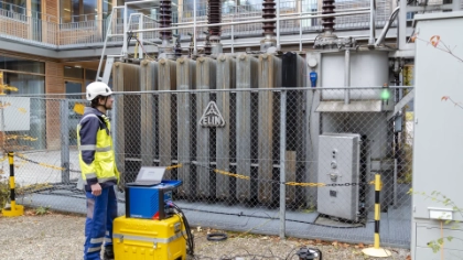
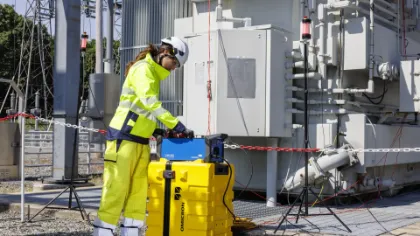
Recommended Solutions
Find The Right Solution for Your Application
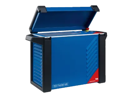
TESTRANO 600 + CP TD12
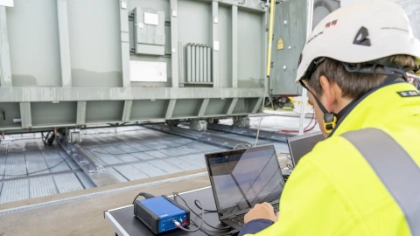
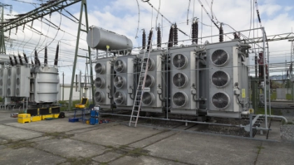
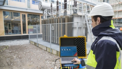
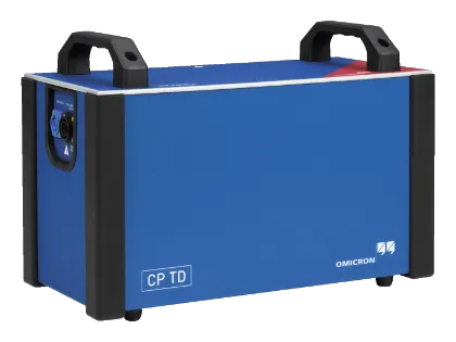
The TESTRANO 600 is a full three-phase testing device that offers the most comprehensive range of diagnostic measurements. The cabling concept is designed to minimize wiring efforts. Operating the OLTC via the device further automates testing, while combining it with the CP TD12 enables dissipation factor measurements. The PTM software lets users combine conventional and advanced transformer diagnostics (dielectric frequency response (DFR) and sweep frequency response analysis (SFRA)) into a single report.
CPX 200 + HVX10
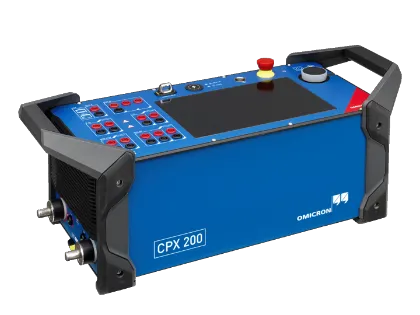
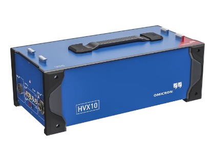
The CPX 200 is a multi-functional test system that offers a wide range of power transformer diagnostic measurements. It also provides testing capabilities for instrument transformers and circuit breakers, as well as an integrated tap changer control to automate ratio and winding resistance measurements. It's equipped with a three-phase voltage output, allowing for accurate turns-ratio and phase-angle measurements. The CPXpert software's dedicated testing workflow allows you to combine results from multiple assets.
MPD 800
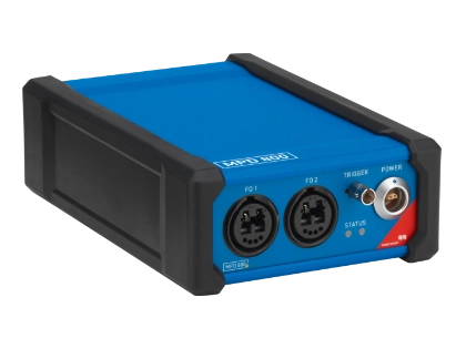
The MPD 800 universal partial discharge (PD) measurement and analysis system represents the next generation of our innovative MPD testing technology. Enhanced hardware and software features enable highly sensitive multi-channel PD measurements and support reliable, industry-standard testing on dry-type and oil-filled power transformers. You can use it for PD measurement and analysis during factory acceptance testing, on-site acceptance testing, and troubleshooting in the field.
FRANEO 800
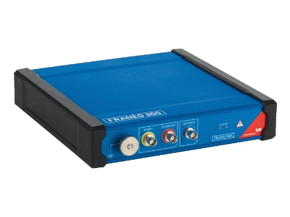
The FRANEO 800 is a portable device for assessing the mechanical integrity of power transformers after transport or exposure to high fault currents. It measures transformer response across a frequency range of 20 Hz to 2 MHz, providing early insight into mechanical conditions that support safer testing, reduced risk, and informed asset management decisions.
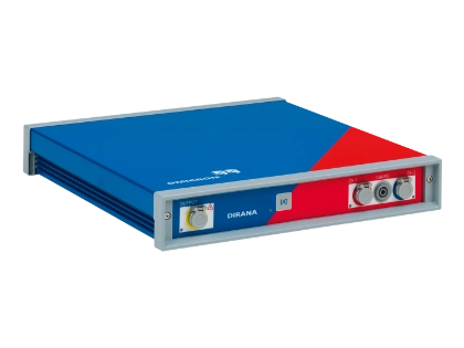
DIRANA
The DIRANA uses dielectric frequency response (DFR) analysis to determine the condition of high-voltage insulation systems such as those in power transformers, bushings, cables, and generators. It automatically analyses and determines the water content and the oil conductivity in different types of cellulose insulation. It can test assets filled with mineral oil, natural or synthetic esters, air, or a vacuum. The measurement results are displayed in categories defined by IEC 60422.
Related Products
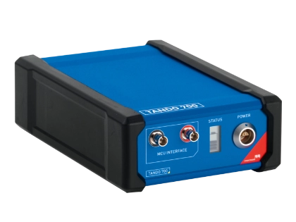
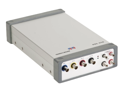
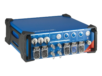
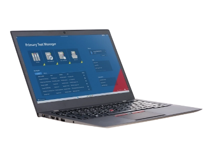
Insights


How should I decide between TESTRANO 600 and CPX 200?
The TESTRANO 600 is a specialist device for power transformer testing that offers the most comprehensive testing capabilities. In addition, the cabling concept is optimized for time efficient power transformer testing.
The CPX 200 is a multifunctional tool that covers a wide range of power transformer testing. If you have to test multiple assets, such as instrument transformers and breakers, the CPX 200 is the device for you.
Is it possible to import third-party SFRA data?
Yes, the PTM software has an import function for dedicated third-party devices as well as the exchange format for IEC and CIGRÉ.
Can I combine electric and acoustic PD measurements in power transformers?
Yes, that's a very powerful tool and is often used when PD is measured in the first phase. Triggering the acoustic localization with the MPD 800 by selecting a particular trigger source in the PRPD makes localization even more sensitive and reliable.
How should I measure PD in environments with strong RF disturbances?
How can I determine moisture content in transformer insulation?
Conventional methods are based on chemical analysis. The disadvantage is that an equilibrium condition must be established, and the transformer must be opened to obtain paper samples.
A non-invasive dielectric frequency response (DFR) analysis with DIRANA allows moisture content to be assessed without expert knowledge or on-site.
What’s the best method for detecting winding deformations?
Mechanical stress from short circuits or transportation can deform windings. The most sensitive method available is: Sweep Frequency Response Analysis (SFRA)
It compares the transformer’s electrical fingerprint to detect:
- Winding movement
- Core displacement
- Mechanical damage
SFRA is non-invasive and highly sensitive – making it an industry standard for integrity verification.
Looking for some guidance on this topic?