

News
How Efficient are Your Testing Processes?
November 4, 2024
Only correctly operating protection relays protect your primary equipment from damage, while contributing to a reliable power grid. This is why protection relays must undergo thorough tests throughout their lifecycle – from development and manufacturing to commissioning and regular maintenance during operation. Our testing solutions enable you to handle related testing tasks with ease, ensuring a highly reliable system.

The rapid evolution of protection relays and the increasing complexity of the power grid confronts protection engineers with the shift toward IEC 61850, as well as new types and functions in modern devices and protection schemes. While virtualized testing approaches may help ease the situation, stricter cybersecurity regulations demand more frequent firmware updates, which lead to shorter protection testing intervals. Our testing solutions allow you to navigate these opportunities and challenges.
The increased demand for electrical energy has pushed existing power lines and substations to their limits. This means utilities are seeing many new projects, major investments, and a spike in testing efforts. Exacerbated by a shortage of specialists, testing efficiency has taken center stage. From creating high quality test plans offline to convenient field testing and automated test result documentation, our modern testing solutions cover the full spectrum.
Today’s protection engineers face a wide range of challenges when testing conventional relays, relays using Sampled Values, or relays with sensor inputs – all of which demand greater testing versatility. Validating the entire protection system with a system-based approach, thoroughly assessing individual devices using settings-based testing, performing primary injection, and verifying critical assets such as current transformers, directly contribute to improved grid reliability. Our solutions are specifically designed to meet these requirements.
As cyber threats in the energy sector continue to rise, regulatory expectations have become much stricter in recent years. Effectively protecting critical infrastructure and ensuring compliance requires considering all attack vectors – including protection relay test sets. Our cyber-hardened CMC 500 minimizes your substation’s vulnerability to cyber threats. We developed the device within our company-wide product security risk management process, also ensuring a transparent, systematic approach to continuously handling and disclosing vulnerabilities.
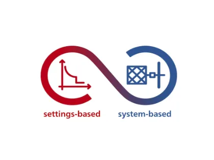
Combining a settings-based and a system-based testing approach is the most efficient way to make sure your protection systems work reliably and exactly as intended.
Settings-based approaches focus on your relay’s protection functions and set values. Flexible templates and comprehensive automation options are key, as they allow you to standardize your workflows and perform tests highly efficiently. This approach ensures your protection devices are tested thoroughly with minimal effort.
System-based protection testing perfectly complements this approach as it focuses on how assets in the protection system interact in realistic conditions. This enables you to easily detect hidden errors in your protection system’s settings, logic and design, ensuring that defined requirements are met.
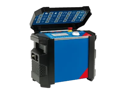
We recommend our CMC 500 solution for unmatched versatility in modern protection relay testing and commissioning. Its modular, multi phase design – combined with IEC 61850 readiness, built in cybersecurity, and powerful automation capabilities – makes it the ideal all in one solution for highly efficient, safe, and future proof relay testing and complete protection system validation.
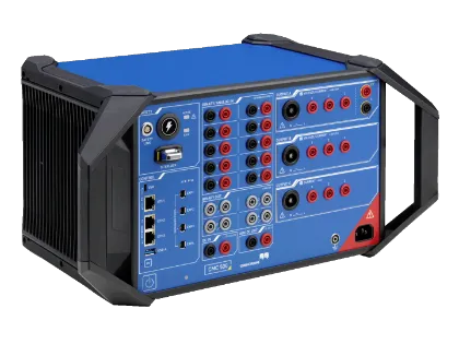
A modular, multi-phase protection relay test set and commissioning tool that is setting new benchmarks for efficiency, safety and cybersecurity
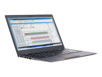
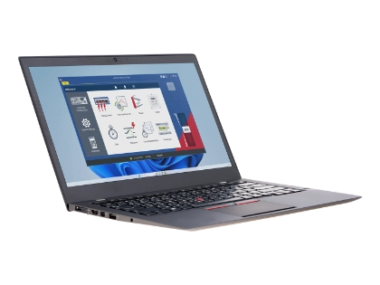
RelaySimTest is a software solution for system based protection testing independent of relay type or manufacturer, validating entire protection systems under realistic conditions.
The CMC 430 is our recommendation if you need an ultra‑portable, high‑precision test solution for modern protection and measurement tasks. At just 8.7 kg (19.2 lb), it delivers powerful current and voltage outputs, hybrid recording, and outstanding accuracy. It is ideal for testing relays and calibrating meters, transducers, power quality (PQ) meters, and phasor measurement units (PMUs) efficiently.
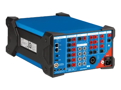
An ultra-portable protection test set and calibrator combining high precision with a lightweight design for testing protection and measurement devices efficiently
RelaySimTest is a software solution for system based protection testing independent of relay type or manufacturer, validating entire protection systems under realistic conditions.
The CMC 310 is our recommended solution if you are looking for a lightweight relay test set capable of fast, basic three-phase testing. Optimized for quick manual workflows, it performs reliable tests on distribution, industrial, and SCADA systems. Additionally, it simplifies anti‑islanding tests in PV installations, providing you with certification compliant test reports.
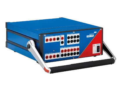
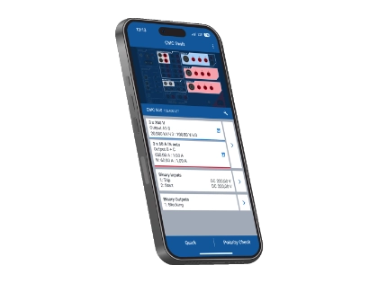
Simple and fast three-phase testing. CMC 310 is an intuitive solution for efficient testing during commissioning and maintenance. It provides easy-to-use test tools optimized for fast, manual field testing.
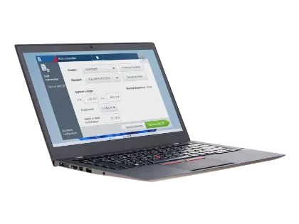
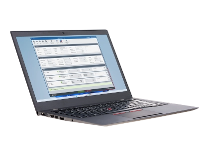
The CMCheck RE software enables fast, automated anti-islanding protection testing for photovoltaic systems. Its workflows and reporting functions are optimized for compliance with national standards.
The daily routine of many protection engineers includes testing protection relays from all generations. While electromechanical and static protection relays are still in use, the design of fully digital substations is slowly gaining momentum. Each relay type requires different capabilities from a protection test set.
Therefore, a flexible test set with multiple current and voltage outputs, as well as the necessary power, is a prerequisite for efficient protection testing. The multiple functions found in protection relays pose an additional challenge. In many instances, our sophisticated testing solutions can avoid time-consuming deactivations of relay functions during testing. We provide options for testing entire protection systems to verify that the whole protection concept is functioning.
IEC 61850 has been successfully established in electrical power systems. Using standardized protocols such as GOOSE, Sampled Values, and MMS, devices and systems can seamlessly exchange data, commands, and measured values. Therefore, when devices from different manufacturers are connected to a common network, they can communicate directly with one another. No additional effort is required for hardwired binary signals, and you can easily reconfigure the system if necessary. IEC 61850 standardization has also made scheduled maintenance testing easier. It is nearly impossible to avoid this standard when implementing fully digital substations.
OMICRON is an IEC 61850 pioneer, providing solutions for testing hybrid and fully digital substations for over 20 years.
Our solutions enable easy, flawless IEC 61850 integration into existing test templates for conventional relays. The reduced wiring required by our solutions makes your tests more efficient than ever.
Since protection relays and primary equipment in medium-voltage substations are closely situated, digital protection relays and low-power instrument transformers (LPITs) can be used in conjunction.
We also offer the LLX1 accessory, which lets you easily test relays with sensor inputs. The LLX1 simulates current and voltage sensors, such as voltage dividers, Rogowski coils, or low-power current transformers, providing the test signal via its low-level outputs.
With the increasing share of renewable energy in the energy mix, utilities face new challenges. Distributed generation, bidirectional load flows, and an increased number of contributors in the energy market represent the current framework conditions. This increase in complexity demands more advanced protection concepts, requiring much more sophisticated testing capabilities from a test set.
Standardized, automated test methods make it easier to perform required settings tests for individual protection elements. Although this makes the increased number of tests more manageable, additional system tests are essential to ensure the stability and reliability of the entire protection system. The system-based approach enables you to account for complex interactions within protection systems, significantly improving testing quality.
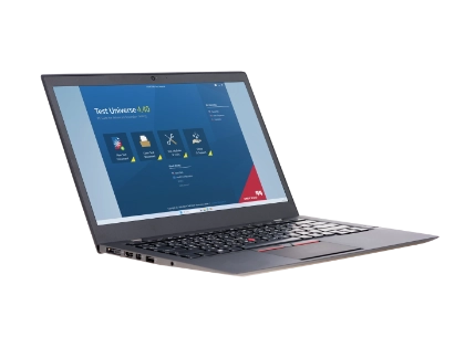
Efficient testing automation saves time, reduces the workload for protection engineers, and avoids error-prone manual interactions. Test Universe and RelaySimTest both offer extensive capabilities for automated testing. CMEngine provides a flexible programming interface for customizing automated workflows and integrating them into your existing testing applications, e.g., type and routine tests for relay manufacturers.
The protection relay’s main function is to detect primary-sided faults or overloads as rapidly as possible. It uses circuit breakers to selectively isolate the affected assets or parts of the grid from the rest of the grid or substation. This protects affected or adjacent equipment and people, keeps outages to a minimum, and plays a key role in providing a highly reliable supply and ensuring high availability. It also enables cost-effective operation, as equipment loss and lengthy outages go hand in hand with enormous costs. Protection relays must be tested regularly to ensure they can function properly during an emergency.
The timing and intervals of tests depend on country-specific regulations and individual strategies defined by a system operator.
Generally speaking, there are four phases in a protection relay’s life cycle, in which different types of tests are appropriate:
The framework conditions for testing during commissioning and regular maintenance that utilities must comply with are specified by country-specific guidelines, such as the Forum Netztechnik/Netzbetrieb (FNN) in Germany, or the North American Electric Reliability Corporation (NERC) in the USA. Protection relay manufacturers then test them for conformity, for example, with the IEC 60255 standard, which defines rules and requirements for measuring relays and protective equipment.
This question can only be answered on a case-by-case basis by individual system operators. It can be stipulated to some extent by country-specific guidelines or regulations. In principle, testing is advisable if after initial commissioning tests, a change is noticed in the protection system, such as a firmware update. However, protection relays remain in operation for long periods of time, and undetected changes may occur. Maintenance intervals and respective testing scopes are defined to detect these types of changes.
Numerous factors must be considered when defining testing intervals, such as:
As these factors are variable, the testing intervals may also change dynamically. Therefore, a uniform testing strategy must be established with documentation integrated into a general quality management system.
When you are testing protection relays, the number one priority is your own safety. When you are preparing to test protection relays, all relevant safety and protection measures must be adhered to before testing commences.
Aspects of protection relay testing
Yes, test plans can be easily adjusted in both directions. All that is required are the licenses for the respective Test Universe modules.
To efficiently adapt test plans to an IEC 61850 test setup, use the System Configuration Language (SCL) data as a starting point. This speeds up the configuration and avoids errors.
In Test Universe, switching between GOOSE and conventional binary I/O can be done by simply adding/removing the GOOSE Configuration module. Afterward, you can simply re-use existing test plans created for conventional protection relays in your digital substations by replacing hardwiring with GOOSE messaging.
Adapting an existing test plan to Sampled Values is also simple, as all analog outputs are configured in a single location. In Test Universe some adaptations to the Test Object may be required, as most test plans in Test Universe are based on secondary values while Sampled Values are defined as primary values. In typical applications, we recommend changing the instrument transformer ratio to 1 and verifying the set residual factors and maximum values.
In end-to-end testing, all ends of a section of a protected line or a protected electrical installation area are tested simultaneously. The testing routines at all ends must be time-synchronized with one another. An end-to-end system-based test can focus on both verifying individual protective functions as well as the correct behavior of the protection system as a whole.
The biggest challenge in end-to-end testing is coordinating the tests. Protection testing solutions that facilitate test execution and document the results from a single side considerably reduce testing complexity and personnel costs. Using system-based end-to-end testing with RelaySimTest lets you run the test from a single end and make adjustments as needed.
Until recently, testing traveling wave protection functions wasn’t carried out during relay commissioning as it proved very difficult. That's why OMICRON developed the TWX1 accessory, the world's first solution for testing traveling wave protection functions in an uncomplicated manner, even with conventional protection test sets.
The test setup is the same as an end-to-end test with the addition of two TWX1 accessories. With RelaySimTest, the test can be carried out from one side, and the results are automatically documented. For this purpose, the system and line data are entered in RelaySimTest. Desired test cases are defined by placing different fault types at desired positions in the power system model. The simulation then automatically calculates the transient signal and the traveling wave pulses. During execution, the CMC test set supplies the transient signal, and the TWX1 accessory superimposes the three-phase voltage and current traveling wave pulses with nanosecond accuracy. The generated signal can be used to effectively test both the traveling wave protection and the location function of traveling wave protection relays.
The IEC 60255-1xx standards specify functional requirements for protection functions. In this standard series the xx stands for the IEEE/ANSI C37.2 protection function number, e.g., IEC 60255-151 specifies requirements for overcurrent protection (51), but also covers related functions like undercurrent (37) and negative sequence overcurrent (46).
The IEC 60255-1xx standards also specify requirements for steady state accuracy and the protection function’s transient performance. Typically, Test Universe is well-suited to verify steady state accuracy, while RelaySimTest covers transient performance.
Many relay manufacturers rely on our solution to perform extensive type testing on their relays and IEDs to verify conformance with these standards. Utilities may perform a subset of such tests to compare and select suitable relay types (acceptance testing).
OMICRON Engineering Services provides support for such testing tasks.
A distinction can be made between the settings-based approach for protection relay testing (currently the most widely used), and the system-based approach. Furthermore, a differentiation can be made between manual and automated execution.
With minimal effort, system-based protection testing can verify that the individual components in a protection system will behave correctly as a group during a fault. This approach enables the detection of hidden errors in the settings, logic and design of protection systems, regardless of the relay type or manufacturer. RelaySimTest provides the tools you need to prepare and run system tests optimally.
Settings-based protection testing focuses on the protection functions and the associated set values of the individual protection relay. Modern protection relays offer thousands of settings, which is why automated testing is far superior to a manual approach. Test Universe provides an extensive range of options for standardization and automation, including fully automatic test report generation. Test plans allow you to test with maximum efficiency. Combining them with the immense functionality of our testing software provides the flexibility necessary to test protection relays and other secondary assets in detail.
Testing approaches
For an in-depth discussion listen to our podcast: Protection Testing – Settings-based and system-based Aproaches
The term automation is often used prematurely, especially when it comes to protection testing. In reality, protection engineers are confronted with assets from many different manufacturers, making it much more difficult to fully automate test procedures. In some cases, suppliers talk about automation when their solution only automates individual parts of protection testing. Hence, caution is advised.
Achieving a high degree of automated protection testing requires adaptable test templates for protection relays from different manufacturers and the ability to flexibly combine individual test modules in test plans. Efficiency can be improved by defining uniform standards for testing protection relays. Fully automated test result documentation is also a basic requirement, as it involves considerable effort when performed manually. Our Protection Testing Library (PTL) allows you to use automated test procedures for a wide range of applications with both Test Universe and RelaySimTest. In addition, these test templates can be easily customized to suit your specific needs, thereby increasing automation even further. Compared to manual protection testing efforts, a reduction of up to 80 percent can be achieved.
We provide a suite of powerful testing software and various additional modules, including
You can tailor these options to your needs or choose one of the four available software packages to operate the CMC 500 and the CMC 430:
Our configuration tool can help select the best combination for your applications.
Interested in a quote?