Overhead Lines

Accurate Impedance Data for Reliable Protection
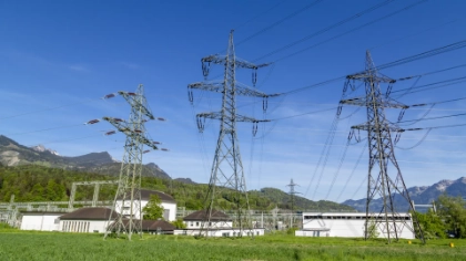
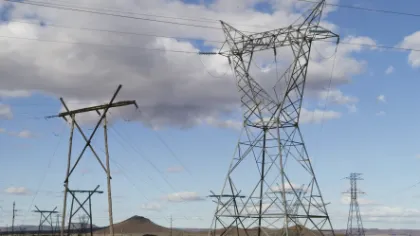
Overhead and transmission lines require precise electrical parameters to ensure dependable protection and safe operation. Line impedance measurements, k-factor testing, and mutual coupling measurements form the basis for accurate distance protection relay settings.
We support transmission line testing for commissioning, verification, and troubleshooting. Measuring positive and zero sequence impedances directly in the field validates your design data, optimizes relay reach, and improves the accuracy of impedance-based fault location.
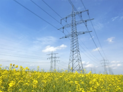
Safe Operation Starts With Proper Grounding
After constructing transmission towers for new overhead lines, validating the grounding system is essential for ensuring safe operation. Over time, towers, foundations, and grounding systems deteriorate, which can compromise safety.
Ground impedance, along with step and touch voltage measurements, helps verify proper grounding performance and identify potential issues early.
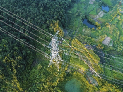
Challenges for Overhead Lines
Inaccurate Line Data
Design values often differ from the real conditions in your system. Tower geometry, conductor arrangement, soil resistivity, and mutual coupling between parallel lines all influence the zero-sequence impedance (Z0).
Relying on incorrect assumptions affects your k-factor calculation and distance protection performance. This may cause unintended protection trips or larger-scale outages if the closest relay fails to reliably trip during a fault.
Mutual Coupling Effects
Parallel and double-circuit transmission lines create zero-sequence mutual coupling. If mutual coupling isn’t measured or compensated for properly, distance relay settings may overreach or underreach during ground faults. This results in reduced selectivity, which may lead to faulty relay trips that compromise your system’s reliability.
Time Pressure and staff shortages
Commissioning and maintenance tests on overhead lines often face tight schedules. Meeting these deadlines requires reliable, field-ready test systems for key measurements, including line impedance, k-factor settings, and grounding performance. Easy-to-use solutions, backed by 24/7 support and training, are another key factor in efficient and reliable workflows.
Repowering / Reconductoring
Overhead lines are often upgraded to increase capacity, for example, by using modern high-temperature conductors, higher voltages and if necessary, improved towers and protection settings. Such upgrades require grounding safety reassessments and accurate data updates to the protection system’s line impedance.
Dynamic Line Rating (DLR)
Modern technologies use sensors, monitoring, and analytics to increase transmission line capacity without rebuilding lines. This can increase fault currents and require adjustments to protection schemes and trip times, making grounding system reassessments necessary to ensure continued safety.
Aging Infrastructure
Overhead lines remain in use for decades, sometimes for over 100 years. Towers, foundations, and grounding systems degrade over time, and nearby developments can alter conditions. Regular checks are essential to ensure proper grounding and keep step and touch voltages within safe limits.
Testing Methods
Overhead Lines Measurement Methods
Line Impedance & k-Factor Measurement
Line Impedance & k-Factor Measurement
Performing a line impedance measurement determines the positive-sequence impedance (Z1) and the zero-sequence impedance (Z0) of overhead lines under real installation conditions. These parameters are required for correct distance protection relay settings and locating faults based on impedance.
Measuring the k-factor (zero-sequence compensation factor) ensures correct ground fault compensation.

Mutual coupling
Mutual coupling
Mutual coupling testing determines the zero-sequence coupling impedance between parallel or double-circuit lines under real conditions. If this coupling is ignored, distance protection may overreach or underreach during ground faults. An additional loop is measured to capture the coupling between the systems. The measured loop impedances provide the basis for an accurate line-parameter calculation for secure and selective protection.
GPR/EPR
Ground Impedance / Ground Potential Rise (GPR/EPR)
The ground impedance test assesses how effectively a transmission tower, its foundation, and the associated grounding system dissipate fault currents into the earth and how much the local ground potential rises during a fault.
High ground impedance results in increased GPR/EPR, which can lead to dangerous step- and touch voltages around the tower, posing risks to people and equipment.

Step- and Touch Voltage Test
Step- and Touch Voltage Test
Step- and touch voltages can also be measured directly. This is especially important if a transmission tower is in a populated area and one needs to ensure that the step- and touch voltages are below permissive limits during a power system fault.
Line Impedance & k-Factor Measurement
Performing a line impedance measurement determines the positive-sequence impedance (Z1) and the zero-sequence impedance (Z0) of overhead lines under real installation conditions. These parameters are required for correct distance protection relay settings and locating faults based on impedance.
Measuring the k-factor (zero-sequence compensation factor) ensures correct ground fault compensation.
Mutual coupling
Mutual coupling testing determines the zero-sequence coupling impedance between parallel or double-circuit lines under real conditions. If this coupling is ignored, distance protection may overreach or underreach during ground faults. An additional loop is measured to capture the coupling between the systems. The measured loop impedances provide the basis for an accurate line-parameter calculation for secure and selective protection.
Ground Impedance / Ground Potential Rise (GPR/EPR)
The ground impedance test assesses how effectively a transmission tower, its foundation, and the associated grounding system dissipate fault currents into the earth and how much the local ground potential rises during a fault.
High ground impedance results in increased GPR/EPR, which can lead to dangerous step- and touch voltages around the tower, posing risks to people and equipment.
Step- and Touch Voltage Test
Step- and touch voltages can also be measured directly. This is especially important if a transmission tower is in a populated area and one needs to ensure that the step- and touch voltages are below permissive limits during a power system fault.
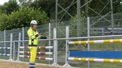
Recommended Solutions
Find The Right Solution for Your Application
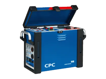
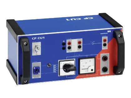
CPC 100 + CP CU1
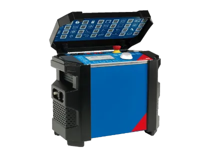
Our CPC 100 and CP CU1 provide a line and ground test system for transmission networks, enabling you to measure positive and zero sequence impedance, calculate the k-factor, and determine mutual coupling under real conditions.
Frequency-selective injection and galvanic isolation enable accurate and safe tests, allowing you to parameterize your distance relays correctly and complete commissioning with confidence. It can also be used to ground transmission line towers.
COMPANO 100 + CIB1
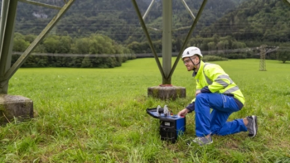
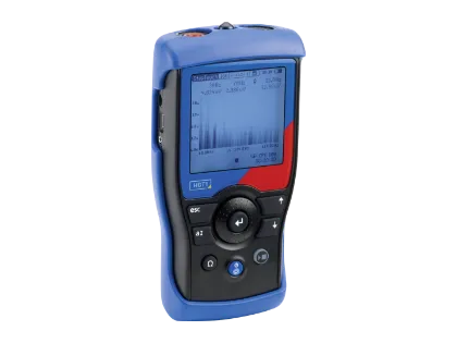
The lightweight, battery-powered COMPANO 100 enables efficient ground impedance measurements and step and touch voltage measurements on overhead line towers to help ensure system safety.
The COMPANO 100 also allows line impedance measurements on short, medium-voltage overhead lines (up to 10 km) without a parallel system. Automatic loop switching, minimal wiring, and integrated safety features simplify testing.
Related Products
Insights


Why should I measure line impedance instead of relying on calculated values?
Calculated values are often based on assumptions about soil resistivity and line configuration. Real measurements determine the actual positive and zero-sequence impedance, as well as the k-factor, ensuring reliable distance protection settings and preventing over- or underreach.
Which parameters can be measured on transmission and overhead lines?
You can measure positive-sequence impedance (Z₁), zero-sequence impedance (Z₀), k-factor, earth impedance, and mutual coupling between parallel lines. These parameters are essential for correct relay parameterization.
What happens if line parameters are incorrect?
Incorrect parameters may lead to zone overreach or underreach, false tripping, or a failure to trip. Accurate measurements reduce the risk of outages and improve grid stability.
How do line impedance measurements improve distance protection?
Measured impedance values enable precise zone setting and k-factor adjustments. This ensures selective tripping and accurate impedance-based fault location under real network conditions.
What is mutual coupling and why does it matter?
Mutual coupling occurs between parallel lines and can influence protection behavior. Measuring it ensures correct relay settings and avoids maloperation.
Can mutual coupling between parallel lines be measured?
Yes, mutual coupling impedance can be determined to account for coupling effects between parallel lines. This prevents protection maloperation caused by induced currents from neighboring lines.
How long does a typical line impedance measurement take?
The setup is straightforward, and measurements are completed quickly thanks to guided workflows and dedicated test templates. Results are available immediately after testing.
What is the advantage of frequency-variable testing?
Testing at variable frequencies suppresses interference and provides more detailed insight into line behavior, increasing measurement accuracy and reliability.
Why does periodically testing the grounding system of transmission towers make sense?
Transmission towers, their foundations, and ground grid deteriorate over time.
For personal safety and avoiding damage to equipment in the surrounding area, the resulting step- and touch voltages must remain below the permissive limits during a fault.
Why should I measure my grounding system after a transmission line has been rewired?
Rewiring is often done to increase the transmission capacity of an overhead line, particularly to address higher short-circuit currents during a fault.
Measuring a transmission tower’s ground grid can provide evidence that the resulting step- and touch voltages will be within permissive limits, even after rewiring.
What is repowering or reconductoring an overhead line, and what are its benefits?
Repowering or reconductoring an overhead line involves upgrading existing transmission infrastructure by replacing conductors or key components to increase capacity and performance. It’s done to meet rising demands, integrate renewables, and improve efficiency. Benefits include higher transmission capacity, reduced losses, lower costs, shorter implementation time, and minimal environmental impact by reusing existing corridors.
Looking for some guidance on this topic?