Substation Wiring
Efficient Substation Wiring Checks
In electrical power systems, all relevant electrical circuits require validation during the commissioning of protection and control systems. This includes instrument transformer wiring, trip and close circuits, logic signals, as well as DC and AC supply connections.
Incorrect polarity, crossed signals, or double grounding can compromise accuracy and protection performance, potentially leading to malfunctions, delayed fault clearing, or unnecessary downtime.
Having the right testing equipment allows your operations and maintenance teams to verify substation wiring safely and efficiently.
Challenges
More Systems, Fewer Experts, Higher Demands
A Growing Power Grid
The grid expansion has introduced many new substations and switchgear installations that must be commissioned. These systems are often delivered by external partners and require thorough verification before energization.
Wiring and configuration errors still occur and can lead to outages, equipment damage, or safety risks if they’re not detected in time.
Qualified Personnel
As the demand for qualified professionals continues to increase, experienced staff are retiring, while fewer newcomers are entering the field. Training new personnel takes time, and complex testing procedures only add pressure.
Clear and efficient testing methods, optional training, and 24/7 technical support can help teams navigate this challenging situation.
High-Level Automation
Efficient modern power networks rely on highly automated protection and control systems. Decisions that were once made manually are now based on data and automated logic.
Wiring errors in secondary circuits may lead to incorrect system behavior, making careful wiring checks for stable grid operation even more essential.
Testing Methods
Innovative Sawtooth-based Testing
This innovative sawtooth-based testing method lets you perform complete end-to-end verification on the entire signal path. Tests can be performed on the primary side of a current transformer (CT) or a voltage transformer (VT), also called a potential transformer (PT), via terminal blocks, protection relays, or meters in the control panels.
A DC-free signal prevents unwanted transformer magnetization and remanence. Since the secondary circuit doesn't require modification, voltage can be measured directly or with a current clamp to ensure maximum safety. Both the polarity and burden can be verified in one step. The waveform display provides additional assurance and valuable troubleshooting insight.
up to 40
%
130
+
20
+
100
µV
Solutions
Wide Ranging Wiring Check Solutions
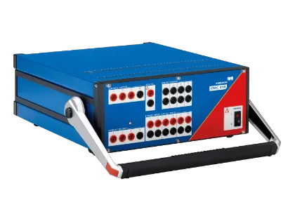
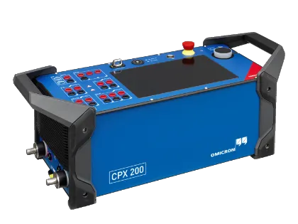
We offer a range of test sets supporting the sawtooth-based testing method. Our lightweight COMPANO 100 is ideal for basic tasks, while the three-phase CMC 500 enables advanced protection testing, and the CPX 200 supports powerful primary injection tests.
Combining these devices with the CPOL3 allows you to perform wiring checks with efficiency. The CPOL3 verifies polarity, identifies phases, and measures True RMS voltage. Its low input impedance mode suppresses coupled signals, and its oscilloscope-like display provides clear, immediate insights into signal behavior.
10
+
12
+
93
24/7
Recommended Solutions
Find The Right Solution for Your Application
Expert Recommendation
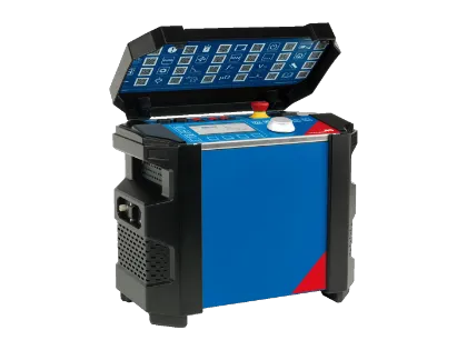
Our mobile, battery-powered COMPANO 100 is ideal for wiring checks requiring AC and DC voltages and currents. Combining the DC-free sawtooth signal with the hand-held CPOL3 polarity checker allows you to check instrument transformer wiring without magnetizing the transformer.
The COMPANO 100 Advanced Package includes all required accessories and necessary software licenses for this application.
Three-phase Testing
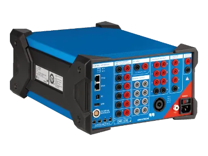
Although our CMC devices are focused on protection testing, they can also be combined with the CPOL3 for wiring checks. From the entry level CMC 310 to the powerful CMC 500, all devices with analog outputs support this application. Both CMControl and Test Universe support adjustable voltage and current output, as well as the CPOL polarity check signal required for this application.
The CMC Swift App also allows you to perform three-phase wiring checks using PhaseID*.
* PhaseID allows you to distinguish between phases based on waveform properties. The CMC Swift App is not available for CMC 310.
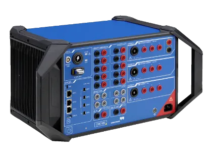
A modular, multi-phase protection relay test set and commissioning tool that is setting new benchmarks for efficiency, safety and cybersecurity
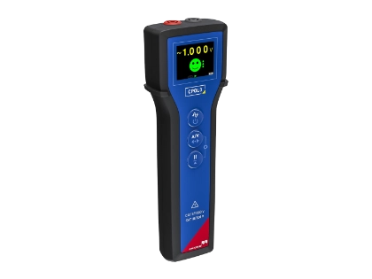
Supports efficient detection of wiring errors in secondary energy system circuits. The CPOL3 is a handheld polarity and wiring checker for instrument transformers, trip, and logic circuits.
Primary injection
The CPX 200 multifunctional test system enables wiring checks for current and voltage transformers using primary and secondary injection.
When used with CPOL3, it safely injects a low-current, DC-free sawtooth voltage signal without magnetizing the transformer cores, enabling you to perform precise wiring verification at every connection point, from the instrument transformer terminals to the burden.
Relevant Facts for Wiring Checks
| COMPANO 100 | CMC series | CPX 200 | CT Analyzer | |
|---|---|---|---|---|
| Supported simultaneous phases | 1 | 3 | 1 | 1 |
| PhaseID* supported | No | Yes* | No | No |
| Battery powered | Yes | No | No | No |
| Weight | 10 kg | 9–16 kg | 11–14 kg | 8 kg |
| Wiring Check Focus | Mobile, universal | 3-phase, universal | Primary injection | Current transformer |
* PhaseID allows you to distinguish between phases based on waveform properties and is supported in the CMC Swift App. This App is currently not available for CMC 310.
Testing Relay Test Switches and Relay Test Blocks
Relay test switches and relay test blocks are installed directly before protection relays or meters, bypassing current transformer circuits by short-circuiting them without interruption, enabling you to test your relays while the system stays energized.
Interrupting a CT circuit could lead to hazardous high voltages capable of causing arc flashes and damage to your equipment. Failures often happen during commissioning when bypass jumpers or connections are missing.
The CPOL3 and COMPANO 100 allow you to safely test each switch during a wiring check by repeatedly activating it. If a brief interruption occurs, the device immediately stops the output and triggers an alarm.
Related Products
Related Videos

What kind of wiring requires checks?
Usually, the secondary wiring from instrument transformers that run from the transformer itself (e.g., in an outdoor substation) through control cabinets to the control room
In the control room, you have to check the control panel wiring / relay panel wiring. This also includes additional circuits such as supply circuits, interlocking circuits, and trip circuits. All of these circuits are part of your substation panel wiring and must be verified carefully.
Why are test signals with DC potentially problematic during wiring checks?
If your secondary circuit includes a CT or VT, a DC component in the test signal can magnetize the transformer core during testing, leaving magnetized remanence after the test.
Remanence can seriously distort the secondary signal during operation. In the worst case, this could even lead to protection malfunctions and power outages.
What can you do to get rid of remanence?
We strongly recommend demagnetizing after testing. For example, you can use the CT Analyzer for this step.
Demagnetization removes the residual flux in the transformer core and prevents unwanted effects during normal operation.
Why should you use a DC-free sawtooth signal for wiring checks?
A DC-free sawtooth signal does not create additional remanence during testing, allowing you to avoid demagnetization after testing in most cases.
However, if you perform the tests after tripping the protection system, you should always demagnetize the CT to ensure reliable operation.
What is the benefit of using a sawtooth signal instead of a sine wave signal?
Both signals are DC-free and do not create additional remanence in a CT.
Sine wave signals are often used for polarity checks, especially on instrument transformers. Detecting polarity requires you to compare the injected signal’s phase with the measured signal. This comparison usually requires running additional test leads back to your test set. In a large outdoor substation, this setup can be quite cumbersome.
A sawtooth signal allows you to detect polarity directly from the waveform. You can identify the polarity based on the signal’s characteristic shape and avoiding running additional test leads back to your test set.
How can you ensure that all three phases are in the correct order at all test points?
You can test each phase individually, for example with the COMPANO 100 or the CPX 200, enabling you to verify the phase assignment step by step.
If you use a three-phase test set such as the CMC 500, you can assign different amplitudes to each phase. This helps you distinguish the phases and confirm the correct order.
Combining the CPOL3 with CMC Swift allows you to apply the PhaseID method. This method modifies the sawtooth signal’s harmonics to differentiate between the phases, providing an additional confirmation that the phases are wired correctly.
Should you use primary or secondary injection for wiring checks?
Both methods offer specific advantages.
Primary injection testing lets you test the complete circuit from end to end, including the instrument transformer.
Secondary injection testing is often easier to perform. You can test the secondary circuit at nominal current and measure the burden simultaneously. However, it’s not a complete end-to-end test.
Interested in a quote?