Instrument Transformers

Reliable Grid Operation Based on Comprehensive Current and Voltage Transformer Testing
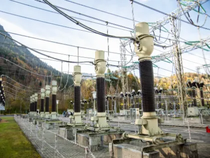
Current and voltage transformers link high-voltage (HV) and medium-voltage (MV) systems to protection, metering, and control equipment. Depending on their design and function, they are classified as current transformers (CTs), voltage/potential transformers (VTs/ PTs), capacitor voltage transformers (CVTs), or low-power instrument transformers (LPITs). Their accurate performance is essential for grid stability and reliable operation.
Our testing solutions range from high-precision test systems for detailed analysis and accuracy assessment to devices for fast functional checks, ensuring key parameters are measured accurately for efficient commissioning, maintenance, and verification.
Challenges
Managing Accuracy and Insulation Risks
Accuracy under real conditions
Instrument transformer accuracy changes with operating burden, current, and voltage. Deviations in ratio error or phase displacement can cause protection maloperation or incorrect revenue metering. Testing under real operating conditions is essential to ensure reliable operation and accurate system performance.
Residual magnetism
Residual magnetism in instrument transformers occurs when magnetic flux remains in the core after testing or grid events. It shifts the magnetization curve, causes premature saturation, and can distort measurement and protection performance. Proper assessment and demagnetization are essential for reliable results.
Burden and wiring issues
Incorrect burden, wiring errors, or polarity mistakes affect transformer performance and may destroy CTs or VTs. Open CT circuits or shorted VT circuits represent severe operational risks and must be identified during commissioning and maintenance.
Model-based Testing Pioneers
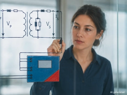
At OMICRON, we have redefined instrument transformer testing with two dedicated solutions: the CT Analyzer for current transformer testing and the VOTANO 100 for voltage transformer testing. Both are based on our patented, model-based approach – an innovation we pioneered.
Instead of complex high-current or high-voltage testing, our technology uses low test signals and advanced algorithms to derive precise transformer models. The result: fast, safe, and highly accurate current and voltage transformer tests – whether on-site or in the lab.
Proven Methods and Advanced Diagnostics
You can perform basic tests for instrument transformer testing – ratio, polarity, burden and insulation resistance – or advanced tests such as winding resistance and excitation curves for deeper insights. Diagnostic methods like partial discharge, dielectric frequency response analysis and tan delta can catch early faults. The result is faster fault detection, clear insight into insulation health, and reliable operation of your protection and metering systems.
14
9
Testing Methods
Basic Tests
Ratio / Ratio Error
Ratio / Ratio Error
Ratio and ratio error measurement verify your instrument transformer’s performance and compliance with design and nameplate specifications. Deviations can indicate shorted turns, open windings, or manufacturing defects. Detecting these errors early prevents protection malfunctions, incorrect system readings, and ensures reliable metering and protection performance.


Polarity
Polarity
A polarity check ensures the correct phase relationship between the primary and secondary values of your instrument transformer. This prevents faulty measurements, relay misoperation, and protection failures. It also verifies that secondary devices are correctly connected, helping detect wiring errors or reversed connections before they impact system reliability.
Knee point voltage
Knee point voltage
Knee-point voltage testing identifies the transition between linear and nonlinear magnetization in the current transformer’s core. Comparing knee points during commissioning helps to verify correct core selection for measurement and protection. This ensures current transformers operate reliably under high currents and prevents protection malfunctions, inaccurate readings, or system errors.
Winding Resistance
Winding Resistance
Winding resistance measurement ensures the electrical integrity of your instrument transformer. It detects issues such as shorted turns, open circuits, or poor connections that can cause overheating, reduced accuracy, or transformer failure. This test identifies potential faults early, helping maintain the reliable operation of protection and metering systems.
Burden
Burden
Burden verification ensures your current and voltage transformers operate within specified limits for maximum accuracy. It measures the influence of cables, connections, and loads on the transformer’s burden, helping detect incorrect connections or faults. Performing this test prevents open-circuit or short-circuit conditions, ensures accurate measurements, and maintains the reliable and safe operation of protection and metering systems.
Insulation Resistance (IR)
Insulation Resistance (IR)
Insulation resistance testing identifies weak points in your instrument transformer’s insulation caused by moisture, aging, or mechanical stress. Detecting these issues early helps prevent electrical breakdowns, equipment failures, and unplanned downtime, while extending the lifespan of your transformers and ensuring the reliable operation of protection and metering systems.
Ratio / Ratio Error
Ratio and ratio error measurement verify your instrument transformer’s performance and compliance with design and nameplate specifications. Deviations can indicate shorted turns, open windings, or manufacturing defects. Detecting these errors early prevents protection malfunctions, incorrect system readings, and ensures reliable metering and protection performance.
Polarity
A polarity check ensures the correct phase relationship between the primary and secondary values of your instrument transformer. This prevents faulty measurements, relay misoperation, and protection failures. It also verifies that secondary devices are correctly connected, helping detect wiring errors or reversed connections before they impact system reliability.
Knee point voltage
Knee-point voltage testing identifies the transition between linear and nonlinear magnetization in the current transformer’s core. Comparing knee points during commissioning helps to verify correct core selection for measurement and protection. This ensures current transformers operate reliably under high currents and prevents protection malfunctions, inaccurate readings, or system errors.
Winding Resistance
Winding resistance measurement ensures the electrical integrity of your instrument transformer. It detects issues such as shorted turns, open circuits, or poor connections that can cause overheating, reduced accuracy, or transformer failure. This test identifies potential faults early, helping maintain the reliable operation of protection and metering systems.
Burden
Burden verification ensures your current and voltage transformers operate within specified limits for maximum accuracy. It measures the influence of cables, connections, and loads on the transformer’s burden, helping detect incorrect connections or faults. Performing this test prevents open-circuit or short-circuit conditions, ensures accurate measurements, and maintains the reliable and safe operation of protection and metering systems.
Insulation Resistance (IR)
Insulation resistance testing identifies weak points in your instrument transformer’s insulation caused by moisture, aging, or mechanical stress. Detecting these issues early helps prevent electrical breakdowns, equipment failures, and unplanned downtime, while extending the lifespan of your transformers and ensuring the reliable operation of protection and metering systems.
Testing Methods
Advanced Tests
Accuracy
Accuracy
Accuracy measurements verify that your instrument transformer complies with design and standard specifications. They provide precise information for the rated voltages and currents, detecting ratio or phase deviations, shorted turns, or capacitor faults. Early detection prevents protection malfunctions, incorrect readings, and financial losses, ensuring reliable metering and protection system operation.
Excitation Characteristics
Excitation Characteristics
The excitation curve analysis verifies the magnetic behavior and performance of your instrument transformer. It ensures the correct operation of protection and metering systems by identifying key parameters such as the knee point. The test helps detect core faults, shorted turns, and early saturation effects, enabling reliable protection performance and accurate system modeling.
PD Analysis
Partial Discharge (PD) Analysis
Partial discharge testing detects early insulation defects in your instrument transformer, caused by voids, moisture, contamination, or design issues. By identifying PD activity, this non-intrusive test prevents insulation failure, costly outages, and unplanned downtime. It ensures the reliable operation of high-voltage transformers and supports both laboratory and on-site diagnostics.

DFR
Dielectric Frequency Response Analysis (DFR)
Dielectric frequency response analysis assesses the moisture content and aging condition of oil-paper insulation in your instrument transformer. High moisture or degraded insulation can reduce breakdown strength, increase losses, and lead to failures. This accurate, non-intrusive method helps detect insulation risks early, preventing catastrophic failures and ensuring reliable transformer operation.

PF / DF
Capacitance & Power Factor/Dissipation Factor (PF/DF)
PF/DF testing evaluates the insulation condition of your instrument transformer. Increased dielectric losses can indicate moisture, contamination, aging, or shorted layers in capacitive stacks. By detecting these issues early, this test helps prevent insulation failures, ensures reliable transformer operation, and supports timely corrective action before costly outages occur.

ALF
Accuracy Limit Factor (ALF)
The ALF (IEC) and terminal voltage (IEEE) indicate whether a protection CT can measure fault currents with sufficient accuracy, considering the specified or connected burden. Accuracy Limit Factor testing ensures the transformer performs reliably under overcurrent and fault conditions, detecting limitations caused by core saturation or non-linear behavior, and helping prevent protection malfunctions while maintaining dependable metering and protection system operation.
Residual Magnetism
Residual Magnetism
Residual magnetism testing detects remanent magnetism in the CT’s magnetic core caused by fault currents, DC components, switching operations, or lightning. Residual magnetism can shift the CT’s operating point, leading to protection relay malfunctions or incorrect current readings. Performing this test ensures stable, reliable transformer performance and accurate operation of protection and metering systems.
Transient CT Parameters
Transient CT Parameters
Transient behavior testing evaluates how your current transformer responds to transient events, such as short circuits or switching operations that introduce DC components. These events can cause asymmetrical magnetization or residual magnetism, potentially leading to protection relay malfunctions. This test ensures CTs operate accurately under nominal and fault conditions, maintaining reliable protection and metering system performance even during extreme events.
Wideband Ratio & Phase Accuracy
Wideband Ratio & Phase Accuracy (Power Quality Testing)
Wideband testing ensures your instrument transformer maintains an accurate performance across the entire frequency spectrum. By evaluating ratio and phase accuracy at harmonics and high-frequency disturbances, this test supports reliable power quality analysis, prevents measurement errors, and helps maintain system reliability, asset availability, and optimal operation for protection, metering and power quality systems.

Accuracy
Accuracy measurements verify that your instrument transformer complies with design and standard specifications. They provide precise information for the rated voltages and currents, detecting ratio or phase deviations, shorted turns, or capacitor faults. Early detection prevents protection malfunctions, incorrect readings, and financial losses, ensuring reliable metering and protection system operation.
Excitation Characteristics
The excitation curve analysis verifies the magnetic behavior and performance of your instrument transformer. It ensures the correct operation of protection and metering systems by identifying key parameters such as the knee point. The test helps detect core faults, shorted turns, and early saturation effects, enabling reliable protection performance and accurate system modeling.
Partial Discharge (PD) Analysis
Partial discharge testing detects early insulation defects in your instrument transformer, caused by voids, moisture, contamination, or design issues. By identifying PD activity, this non-intrusive test prevents insulation failure, costly outages, and unplanned downtime. It ensures the reliable operation of high-voltage transformers and supports both laboratory and on-site diagnostics.
Dielectric Frequency Response Analysis (DFR)
Dielectric frequency response analysis assesses the moisture content and aging condition of oil-paper insulation in your instrument transformer. High moisture or degraded insulation can reduce breakdown strength, increase losses, and lead to failures. This accurate, non-intrusive method helps detect insulation risks early, preventing catastrophic failures and ensuring reliable transformer operation.
Capacitance & Power Factor/Dissipation Factor (PF/DF)
PF/DF testing evaluates the insulation condition of your instrument transformer. Increased dielectric losses can indicate moisture, contamination, aging, or shorted layers in capacitive stacks. By detecting these issues early, this test helps prevent insulation failures, ensures reliable transformer operation, and supports timely corrective action before costly outages occur.
Accuracy Limit Factor (ALF)
The ALF (IEC) and terminal voltage (IEEE) indicate whether a protection CT can measure fault currents with sufficient accuracy, considering the specified or connected burden. Accuracy Limit Factor testing ensures the transformer performs reliably under overcurrent and fault conditions, detecting limitations caused by core saturation or non-linear behavior, and helping prevent protection malfunctions while maintaining dependable metering and protection system operation.
Residual Magnetism
Residual magnetism testing detects remanent magnetism in the CT’s magnetic core caused by fault currents, DC components, switching operations, or lightning. Residual magnetism can shift the CT’s operating point, leading to protection relay malfunctions or incorrect current readings. Performing this test ensures stable, reliable transformer performance and accurate operation of protection and metering systems.
Transient CT Parameters
Transient behavior testing evaluates how your current transformer responds to transient events, such as short circuits or switching operations that introduce DC components. These events can cause asymmetrical magnetization or residual magnetism, potentially leading to protection relay malfunctions. This test ensures CTs operate accurately under nominal and fault conditions, maintaining reliable protection and metering system performance even during extreme events.
Wideband Ratio & Phase Accuracy (Power Quality Testing)
Wideband testing ensures your instrument transformer maintains an accurate performance across the entire frequency spectrum. By evaluating ratio and phase accuracy at harmonics and high-frequency disturbances, this test supports reliable power quality analysis, prevents measurement errors, and helps maintain system reliability, asset availability, and optimal operation for protection, metering and power quality systems.
Find The Right Solution for Your Application
Full Testing, Calibration and Assessment of HV and MV Current Transformers
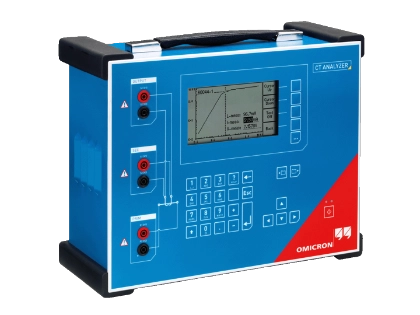
CT Analyzer is our fast and precise test set for evaluating CT performance. It measures equivalent circuit parameters and automatically calculates all relevant electrical performance data, including transient behavior, while assessing protection and metering CT parameters. Lightweight (< 8 kg / 17 lbs) and suitable for both on-site and laboratory testing of single- and multi-ratio CTs.
Full Testing, Calibration, and Assessment of HV and MV Voltage Transformers
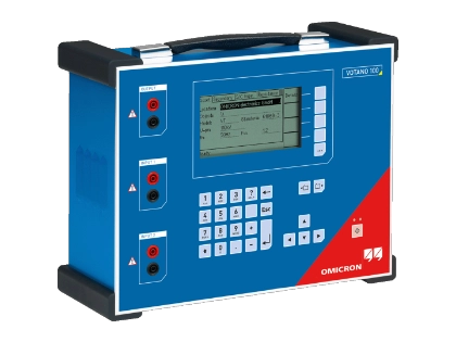
VOTANO 100 is our portable test set for MV and HV voltage transformers. It performs fast performance checks, class verification, and field-calibration of inductive VTs and CVTs for protection and metering applications. Compact (15 kg / 33 lbs) and designed for reliable, efficient use both in the field and in the lab.
Comprehensive Insulation Diagnostics for HV and MV Instrument Transformers
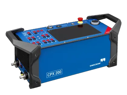
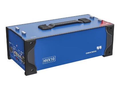
The CPX 200 + HVX10 is a powerful, compact test set for instrument transformers, enabling insulation resistance, capacitance, and power factor/dissipation factor measurements without rewiring. Its wide frequency range (1 to 600 Hz), high accuracy, and automatic PI/DAR calculation provide precise insights into insulation condition, enabling early detection of moisture, dielectric losses, or shorted capacitive layers. Designed for both field and lab use, it supports multi-bushing testing and trend analysis, making insulation diagnostics efficient, reliable, and proactive.
Multifunctional HV and MV Instrument Transformer Testing
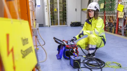
CPX 200 is our compact, multifunctional test system for fast functional instrument transformer checks. It performs ratio, excitation, winding resistance, and burden measurements in a single setup, enabling efficient verification for current transformer performance. It also enables precise testing for voltage transformer ratio, burden, and polarity. Designed for both on-site commissioning and maintenance, it delivers precise, reliable results with a portable, easy-to-transport design and minimal setup.
Protection Testing with Basic Functional Instrument Transformers Checks
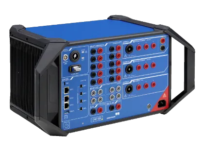
CMC 500 is our multifunctional protection relay test set that also supports commissioning-focused functional checks on current transformers. With the CMC 500 CT check, you can perform basic tests of ratio, polarity, burden, knee-point, winding resistance, and automatic demagnetization – all in a simple, automated workflow.
Basic Testing for Current and Voltage Transformers in Substations
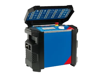
COMPANO 100 is our lightweight and versatile test set for basic testing in electrical substations. It can perform CT and VT ratio checks, polarity verification, and burden measurements using primary or secondary injection. Ideal for quick and basic commissioning and maintenance directly in substations, with battery operation and a compact, field-ready design.
Testing Solutions for all Types of Instrument Transformers
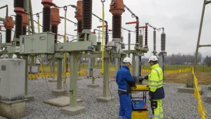
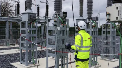
Our testing systems enable comprehensive tests for high-voltage (HV) and medium-voltage (MV) instrument transformers, including current transformers (CTs), voltage/potential transformers (VTs/PTs), capacitor voltage transformers (CVTs), and low-power instrument transformers (LPITs).

Related Products
Energy Talks
Related Podcast Episodes





What are instrument transformers and why is testing them important?
Instrument transformers, current transformers (CTs), and voltage transformers (VTs) convert high primary currents and voltages into standardized secondary signals used by protection relays, metering systems, and monitoring equipment. Regular instrument transformer testing ensures measurement accuracy, reliable protection operation, and proper insulation condition. This helps prevent incorrect protection trips, metering errors, and equipment failures in power systems.
What are the most common electrical tests for CTs and VTs?
Typical electrical accuracy tests include ratio accuracy and phase displacement measurement, excitation curve measurement and knee-point voltage determination, winding resistance testing, burden measurement, and polarity verification. These tests confirm that the instrument transformer meets its specified accuracy class for protection and metering applications.
What is the difference between direct and model-based testing?
Direct testing verifies transformer performance by injecting high current or voltage into the transformer’s primary circuits. This method often requires large primary injection equipment. Model-based testing combines low-level test signals with mathematical models to determine parameters such as ratio error, phase displacement, excitation characteristics, and the accuracy limit factor (ALF). This approach enables highly accurate measurements with portable equipment, making it well-suited for on-site testing.
What is standard-compliant testing and assessment?
Standard-compliant testing verifies instrument transformer performance in accordance with international standards such as IEC and IEEE. OMICRON testing solutions automatically measure parameters such as ratio accuracy, phase displacement, excitation characteristics, and knee-point voltage and compare the results with the limits defined in these standards. This provides clear pass/fail assessments and automatically generated standardized reports for commissioning, maintenance, and compliance documentation.
Can instrument transformer testing be performed on-site?
Yes, modern portable testing systems allow instrument transformer testing directly in substations and power plants. On-site testing supports commissioning, maintenance, and post-fault diagnostics. It enables rapid installation and performance verification without removing equipment from its service location.
What is the difference between detailed testing and functional checks?
Detailed testing evaluates the transformer’s complete performance, including ratio accuracy, excitation characteristics, knee-point voltage, and insulation condition. Functional checks focus on verifying basic parameters such as ratio, polarity, burden, and wiring correctness. These checks are typically performed during installation verification or routine maintenance to confirm correct operation.
How often should instrument transformers be tested?
Testing frequency depends on transformer type, criticality, and operating environment. Typical schedules include commissioning tests, periodic maintenance inspections, and post-fault diagnostics to ensure continued measurement accuracy and reliable protection operation.
Looking for some guidance on this topic?