Test Universe Modules
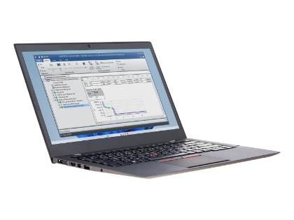
Manual checks, thresholds, logic, replay, and wiring
Dedicated modules for relay-function verification
Test GOOSE, Sampled Values, and SCADA reporting
Use your CMC to test and calibrate energy meters, electrical transducers and PQ analyzers
Visualize and analyze recorded disturbance signals
As per your typical testing needs and system-based application
Generic Testing
Generic test modules support your everyday commissioning, maintenance, and troubleshooting tasks for protection relays and related equipment. You can use them to perform manual checks, determine thresholds, verify timing and logic, replay transient fault records, and validate signal marshalling and wiring. Each module supports a specific engineering task, from quick interactive checks to structured and repeatable test workflows.
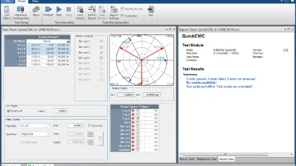
QuickCMC → Manual testing
Perform fast PC-controlled manual tests for protection relays, measurement transducers, and related equipment. You can control all available CMC voltage and current outputs in magnitude, phase, and frequency. Use QuickCMC for setup verification, initial assessment, troubleshooting, and primary injection check.
Flexible signal setup
- Define outputs as fault values, symmetrical components, or powers
- Adjust values numerically or in the phasor diagram
Threshold and timing checks
- Use steady-state, step, ramp, and pulse-ramping functions
- Determine pick-up, drop-off, and starting values
- Monitor binary inputs, measure timing, and create customizable reports
Analysis and reporting
- Display calculated residual values and symmetrical components
- Add selected measurements and assessments to the report
Ramping → Precise threshold testing
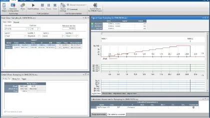
Determine pick-up, drop-off, and switching hysteresis with automated ramp sequences. You can ramp the magnitude, phase, or frequency of the CMC voltage and current output.
Flexible ramp definition
- Define consecutive ramp segments as needed
- Run two simultaneous ramps for independent variables, such as V/Hz
- Ramp components of the same output signal, including fundamental and harmonic values
Threshold assessment
- Use step-back for quick and precise threshold testing
- Automatically assess pick-up and drop-off ratios from rising and falling ramps
- Use Time Signal View for visual control and further analysis
Pulse Ramping → Pick-up testing
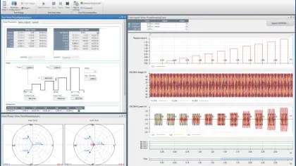
Determine pick-up values for multifunctional relays with overlapping elements. Use pulsed ramp signals to test selected elements without disabling related functions. You can also test rate of change of frequency (ROCOF) protection functions.
Targeted element testing
- Test pick-up values of high-set elements without disabling related functions
- Avoid high continuous current for electromechanical relays with high instantaneous settings
ROCOF testing (rate of change of frequency, shown as df/dt)
- Define sequences for rate of change of frequency protection functions
- Return to default stage between pulses to avoid leaving the frequency range
State Sequencer → Logic and Timing
Build state-based test sequences to verify relay operating times, logic behavior, and event-driven transitions. Use State Sequencer for trip time verification, automated testing of complex protection logic with more than 100 states, and time-synchronized end-to-end testing with two CMC devices.
Precise state setup
- Set output values individually for each state
- Define phase angles relative to the previous state
- Use the integrated Fault Calculator with impedance view
- Configure trigger conditions for state transition
Automatic assessment
- Define expected relay response per state with tolerance options
- Define time assessment for events or intervals
Result analysis and reporting
- Analyze relay response with traces, zoom, and data cursors
- Adjust the level of detail in the report
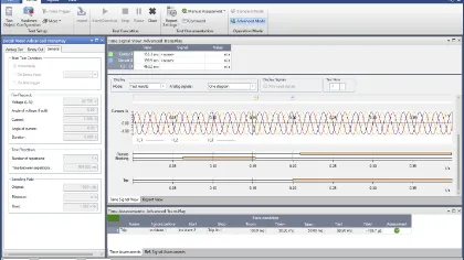
(Advanced) TransPlay → Transient Playback
Replay Common Format for Transient Data Exchange (COMTRADE), PL4, and CSV transient records to test relay behavior with realistic fault signals. Advanced TransPlay adds event marking, automatic assessment, signal processing, binary output replay, and synchronized playback.
Transient signal replay
- Load, view, and replay records from protection relays, fault recorders, EnerLyzer, or simulation software
- Record relay response and generate test reports
Advanced assessment
- Mark fault inception, start, trip, and other key events
- Measure relay response times with automatic assessment
Enhanced playback control
- Modify amplitudes, repeat signal sections, and replay binary signals
- Synchronize playback via Precision Time Protocol (PTP), Global Positioning System (GPS), Inter-Range Instrumentation Group time code B (IRIG-B), or binary input pulse
Annunciation Checker → Signal marshalling
Verify that protection device status signals and analog values appear at the correct locations. Create a signal/location test grid to check marshalling, wiring, and indication behavior during commissioning.
Structured test planning
- Create a checklist for signal verification before testing
- Include visual inspection checks
- Adapt the signal/location grid during execution
Flexible signal checks
- Trigger relay signaling by shots or steady state outputs
- Test in any order, by signal or by location
- Define automatic assessments where appropriate
- Review summarized results in a tabular test report
Protection Function Testing
Verify specific relay functions with dedicated test logic, protection-oriented diagrams, and automatic assessment. Use familiar views such as I/t, Z-plane, P-Q, synchronizing, and differential characteristics to validate settings, timing, thresholds, and operating behavior consistently.
Overcurrent → Overcurrent testing
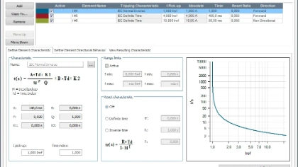
Fast, reliable, and highly automated testing of directional and non-directional overcurrent protection functions. Complementary Overcurrent Characteristics Grabber helps extract overcurrent characteristics from data sheets.
Testing all overcurrent protection characteristics
- Test ANSI/IEEE C37.2 functions 37, 50, 51, 67, and 76 with dedicated overcurrent workflows
- Automatic test shot assessment considering all active elements
- Simultaneous testing of multiple fault types, including line-to-line and line-to-ground faults
- Test point definition in absolute values or relative to element thresholds
- Integrated pick-up/drop-off testing
- Options to consider pre-fault (load) current and decaying DC component
Flexible characteristic definition
- Use predefined IEC and IEEE relay and recloser characteristics
- Create or import custom curves for manufacturer-specific characteristics
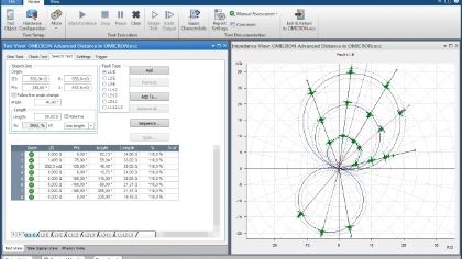
(Advanced) Distance → Distance protection testing
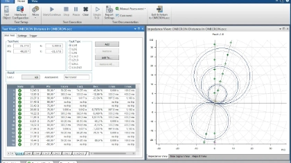
Test distance protection functions in the impedance plane with graphical zone characteristics, fault-loop-specific test points, and automatic pass/fail assessment.
Distance key features
- Test interactively using the graphical characteristic representation
- Define test points easily for all fault loops
- Automatically assess, visualize and report results
Advanced Distance extends these capabilities with advanced testing, automation and analysis features:
Advanced reach and zone testing
- Use Search tests to determine zone reaches automatically
- Use Check tests for quick verification of tolerance boundaries
- Define test points relative to zone borders
Advanced modelling and analysis
- Use a constant source impedance ratio (SIR) test model
- Analyze trip-time distribution and spread in the Z/t diagram
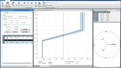
VI Starting → Voltage dependent starting
Test voltage-dependent overcurrent starting characteristics used in distance relays.
Automatic VI starting tests
- Verify existing starting characteristics
- Use Search mode to determine the characteristic
- Determine pick-up and drop-off values
- Test separate phase-to-phase and phase-to-ground characteristics
- Operate intuitively with graphical test representation
Autoreclosure → AR sequence testing
Test autoreclosure functions in protection relays with automatically configured successful and unsuccessful sequences. Verify sequence timing, relay behavior, and final trip criteria for overcurrent, distance, or line differential relays.
Efficient sequence setup
- Define faults by type and fault quantities
- Use the Fault Calculator to generate output voltages and currents
Protection-specific testing
- Test AR functions in overcurrent, distance, and line differential relays
- Specify distance protection faults directly in the impedance plane
- Test single- and three-phase autoreclosure functions
Clear sequence assessment
- Evaluate key criteria such as three-phase final trip
- Review the time sequence and assessed event list in the report
Diff Configuration → stability testing
Test the stability of differential protection functions for external faults. Use relay readings of phase currents and differential values to verify correct setup of the protection function.
Key features:
- Model the protected object, including 2-winding transformers, 3-winding transformers, generators, motors, and busbars
- Verify set-up and configuration before starting characteristic tests
- Check current transformer (CT) starpoint grounding, zero-current elimination, and interposing transformers
- Document differential currents seen by the relay for external faults
- Support end-to-end testing with two CMCs
- Test 3-winding transformers with currents on all 3 sides
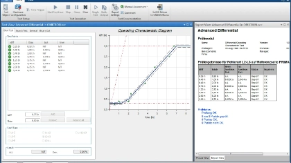
Diff Characteristic → Operating characteristic testing
Verify the characteristic of differential protection relays for phase and ground faults. Use the module Diff Operating Characteristic to test the differential characteristic and the module Diff Trip Time Characteristic to verify trip times.
Key features:
- Support a wide range of restraint-current calculation methods
- Automatically consider effects from zero-current elimination and vector group transformation
- Display characteristics and results graphically
- Use Search tests to determine the characteristic automatically
Diff Harmonic Restraint → Harmonic blocking testing
Use Diff Harmonic Restraint to verify that your differential protection blocks correctly when harmonic content indicates non-fault conditions. This helps you confirm that the relay does not trip for differential currents caused by inrush, current transformer (CT) saturation, or overexcitation.
You can test harmonic restraint behavior using harmonic criteria such as 2nd harmonic for inrush or 5th harmonic for overexcitation. For blocking functions based on current waveform analysis (CWA), use RelaySimTest instead.
Key features:
- Visualize characteristics in the harmonic restraint plane where the differential current is drawn over the harmonic content of the test current.
- Select the harmonic order and phase angle to be tested
- Run tests using defined test points, Search tests, or Check tests
(Advanced) Power → P-Q plane testing
Test power-based protection functions where visualization and assessment in the P-Q or S-φ domain is required.
Efficient testing of power protection functions
- Test generator protection such as reverse power, forward power, underexcitation, out-of-step protection
- Test distributed energy resources (DER) protection functions such as Q-V protection
- Define shots as P-Q, S-φ, or S-cos φ values
- Visualize and test overlapping protection functions
- Display the generator diagram together with protection characteristics
- Assess power shots automatically
Advanced Power adds dynamic ramps, trajectories, frequency variation, and impedance-to-power mapping.
- Testing with power and frequency ramps
- Test pick-up/drop-off thresholds of power functions using smooth ramps
- Test load-shedding schemes based on power or frequency
- Verify configuration of protection functions reacting for unwanted operating conditions
Impedance pane and mapping to power
- Test power swing blocking distance protection
- Test underexcitation protection with Mho circles using impedance criteria
Synchronizer → Synchronizing device testing
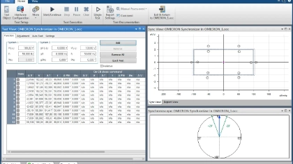
Test synchronizing devices and synchro-check relays by simulating two systems before breaker closing. Keep the mains fixed while controlling generator-side voltage magnitude and frequency.
Synchronizing window assessment
- Detect the circuit breaker (CB) closing command automatically
- Evaluate synchronization using CB closing time and window limits
Generator-side control
- Ramp voltage magnitude and frequency with generator time constants
- Use frequency and voltage adjustment commands f↑, f↓, V↑, and V↓ to control the second voltage output
Dynamic synchronization review
- Simulate system behavior with dynamic generator models
- Monitor command sequences, voltage/frequency changes, and synchronoscope display
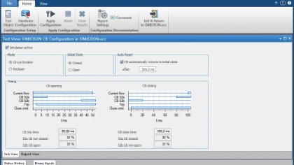
CB Configuration → Breaker simulation
Simulate circuit breakers or recloser auxiliary contacts during protection relay tests. Provide real-time 52a and 52b contact responses to trip and close commands through CMC firmware control.
Auxiliary contact simulation
- Simulate CB or recloser contacts when testing protection relays that monitor these contacts
- Support one-pole or three-pole operation where binary I/O allows
- Works in the background - can be combined with all Test Universe modules
Clear timing visualization
- Most modules can visualize the CB auxiliary contacts within their Time Signal View.
IEC 61850 and Digital Substation
These modules extend Test Universe testing into IEC 61850-based substations. Use Generic Object Oriented Substation Event (GOOSE), Sampled Values, and Client/Server communication to validate protection behavior, Intelligent electronic device (IED) responses, Supervisory Control and Data Acquisition (SCADA) reporting, and process bus signals in the same test environment.
GOOSE → IEC 61850 messaging
This license enables a CMC test set for communication with the GOOSE messages on the Substation Network.
The mapping and the setup are done in Test Universe and RelaySimTest. Configuration parameters can be imported from System Configuration Language (SCL) files.
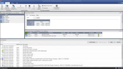
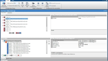
Once GOOSE messages are configured in the Test Universe GOOSE configuration module, the CMC test set interacts with the status data in GOOSE messages as if they were wired to the binary inputs and outputs of the CMC: received (subscribed) GOOSE messages actuate the binary inputs and binary output state changes initiate GOOSE message publication. This allows for easy usage of GOOSE messages in all relevant Test Universe modules.
Sampled Values → IEC 61850 process bus testing
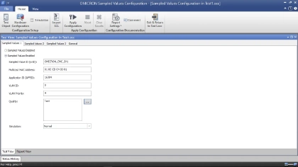
This license enables a CMC test set to simulate merging units publishing Sampled Values streams according to IEC 61869-9 and IEC 61850-9-2 Ed2.1.
Configuration parameters can be imported from SCL files. Test Universe supports up to 3 streams, RelaySimTest up to 4 streams. In Test Universe Sampled Values are configured and mapped in the Hardware Configuration and then used by all modules of an OMICRON Control Center (OCC) test plan. This facilitates reusing test plans when switching between Sampled Values and conventional voltage and current sources.
IEC 61850 Client/Server → SCADA communication testing
IEC 61850 Client/Server performs protection testing using IEC 61850 SCADA (MMS) reports. This allows you to verify that the IED issues the correct reports to the SCADA system. The module has access to the IED’s entire data model and can interrogate any data attribute during testing. It also controls the IED’s operation mode to isolate the device under test.
Measurement & Power Quality (PQ) Testing
Use these modules to extend Test Universe beyond protection relays to energy meters, measurement transducers, and power quality analyzers. Use the CMC as a precise signal source to run manual or automated tests, verify measured outputs, generate PQ phenomena, and document results with structured assessment.
Meter → Energy Meter testing
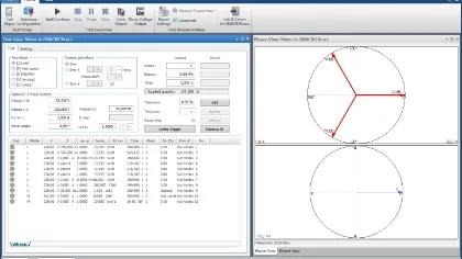
Test energy meters using high-accuracy CMC voltage and current outputs. Capture meter pulses for automated closed-loop testing, including assessment against defined tolerances.
Flexible meter checks
- Run load, mechanism, gated mechanism, injection, no-load, and creep tests
- Repeat failed steps without rerunning the full test
Broad test coverage
- Test single-phase, 3-wire, and 4-wire meters with balanced or unbalanced loads
- Generate sine, harmonic, or DC current waveforms
Clear assessment
- Display voltage, current, and power phasors
- Report meter error, pass/fail results, and standard deviation per test point
Explore more about energy meter testing options with CMC test sets
Transducer → Transducer testing
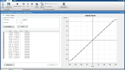
Test electrical measuring transducers using standard outputs such as 0...10 V and 4...20 mA. Save time during commissioning and maintenance by using the same multifunctional CMC test set and software for both transducer and protection testing.
Broad function coverage
- Test real, reactive, apparent power, voltage, current, frequency, phase, and DC quantities
- Support signed average current and three- and four-wire systems, and open-loop display checks
Flexible characteristic testing
- Verify linear, compound, quadratic, symmetrical, and non-symmetrical characteristics
- Generate sine, harmonic, or DC-superimposed signals for realistic input conditions
Automatic assessment
- Run test point tables or manual adjustment checks
- Display transfer characteristics, error, average error, and pass/fail results
Explore more about testing options for electrical measuring transducers with CMC test sets
PQ Signal Generator → PQ analyzer testing
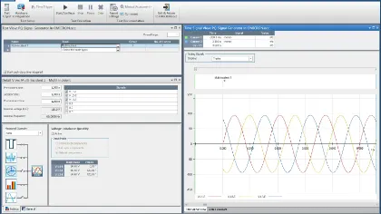
Verify the functionality and accuracy of power quality meters and analyzers by creating power quality phenomena according to IEC 61000-4-30.
Power quality phenomena
- Generate frequency, voltage, flicker, dips, swells, interruptions, transients, unbalance, and rapid voltage changes
- Combine phenomena for comprehensive PQ analyzer testing
Comprehensive test plan library
- Complementary sample tests according to IEC 62586-2
(Modules used: PQ Signal Generator, Advanced TransPlay, Ramping, State Sequencer)
Note: We recommend EnerLyzer for analysis and troubleshooting during testing of PQ analyzers.
Transient Signal Analysis and Supporting Tools
Use these tools to analyze transients, generate harmonic signals, and run multiple OCC test plans in sequence. Analyze disturbance data, create specialized signals, and repeat tests more efficiently.
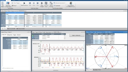
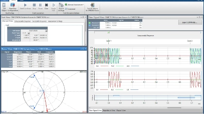
TransView → Signal visualization and analysis
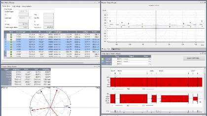
Visualize and analyze analog and binary signals recorded by relays, CMC test sets with EnerLyzer, and disturbance recorders. TransView processes COMTRADE data graphically and calculates system quantities such as residual quantities, impedances, power vectors, root mean square (RMS) values, and symmetrical components.
Multiple views for detailed analysis
- Time Signal: View analog quantities as primary or secondary, instantaneous or RMS values
- Phasor diagrams: View measured and calculated quantities as complex phasors at defined points in time
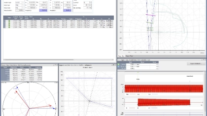
- Locus diagrams: Analyze impedance locus diagrams together with trip zones of distance protection (imported from Test Object)
- Harmonics: View harmonics as bar graphs based on a full-cycle Discrete Fourier Transformation (DFT)
- Value table: Compare multiple signal values at cursor positions
Analyze recordings from different sources
- Investigate recordings from both ends of a line together
- Compare records from different relays for comprehensive network disturbance analysis
Harmonics → Harmonic signal generation
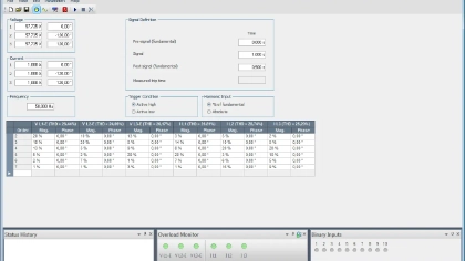
Simple tool to generate voltage and current test signals with a fundamental component and superimposed harmonics up to 3 kHz. Define three voltage and three current fundamentals with multiple harmonics entered as percentages or absolute values.
Note: this complementary tool is not a Test Universe module and does not run within an OCC test plan.
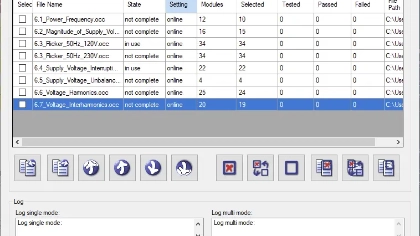
OCC Batch → Batch execution of OCC plans
Run multiple OMICRON Control Center (OCC) documents sequentially for efficient acceptance testing or continuous integration workflows.
Relay manufacturer
- Use OCC Batch for continuous integration (CI) testing during development
Utilities and test laboratories
- Use OCC batch for efficient acceptance testing with a high number of test plans
Packages
How Modules are Packaged
Test Universe modules are available in four software packages: Essential, Standard, Enhanced, and Complete. Each package expands the testing scope step by step, from core manual and automated testing to dedicated protection-function testing, system-based validation, IEC 61850 applications, measurement-device testing, and signal analysis.
Teams can start with the package that matches their current testing needs and extend later with additional modules or add-on packages.
Essential Package
Essential provides the core Test Universe modules for manual testing, state-based sequencing, ramping, harmonic signal generation, breaker contact simulation, transient playback, and OCC-based test plans. It is the entry point for foundational testing and can serve as the base for a customized Test Universe configuration.

Standard Package
Standard adds the modules typically used for settings-based protection testing. It extends Essential with modules for pulse ramping, managing, outputting COMTRADE files, and verifying messages and signals. Furthermore, it adds modules for dedicated protection functions such as overcurrent, distance, differential, and power.
Best suited for teams that need structured relay testing with protection-specific workflows, characteristic-based views, and reusable test methods.
Enhanced Package
Enhanced extends Standard with RelaySimTest for system-based testing, modules for transient ground-fault simulation and synchronized-device testing, and the CMEngine programming interface. It is designed for teams that need to go beyond settings-based relay tests and validate behavior in broader system scenarios.


Complete Package
Complete includes the full software scope for operating CMC test sets. It covers protection testing, IEC 61850 testing, measurement-device testing, power quality testing, transient recording, signal analysis, and advanced RelaySimTest features.
Best suited for teams that need the broadest application range across conventional substations, digital substations, measurement applications, and advanced testing workflows.
Essential provides the core Test Universe modules for manual testing, state-based sequencing, ramping, harmonic signal generation, breaker contact simulation, transient playback, and OCC-based test plans. It is the entry point for foundational testing and can serve as the base for a customized Test Universe configuration.
Standard adds the modules typically used for settings-based protection testing. It extends Essential with modules for pulse ramping, managing, outputting COMTRADE files, and verifying messages and signals. Furthermore, it adds modules for dedicated protection functions such as overcurrent, distance, differential, and power.
Best suited for teams that need structured relay testing with protection-specific workflows, characteristic-based views, and reusable test methods.
Enhanced extends Standard with RelaySimTest for system-based testing, modules for transient ground-fault simulation and synchronized-device testing, and the CMEngine programming interface. It is designed for teams that need to go beyond settings-based relay tests and validate behavior in broader system scenarios.
Complete includes the full software scope for operating CMC test sets. It covers protection testing, IEC 61850 testing, measurement-device testing, power quality testing, transient recording, signal analysis, and advanced RelaySimTest features.
Best suited for teams that need the broadest application range across conventional substations, digital substations, measurement applications, and advanced testing workflows.
Need help deciding?