
Safe Timing Measurements on Circuit Breakers Using Grounding on Both Sides
Reliable measurements without compromising safety
Timing tests play a crucial role in evaluating the condition and operational performance of high-voltage circuit breakers. They deliver important insights into switching behavior and overall asset health. As substation safety standards rise, testing must ensure both precise results and maximum engineer protection.
The challenge of grounding both sides
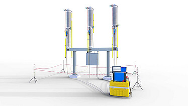
The traditional voltage-based timing measurement method generally permits grounding on only one side of the circuit breaker. In energized substations, this can lead to dangerous voltages appearing on metallic parts that are not grounded. To carry out timing tests on high-voltage circuit breakers with both sides grounded, a different test method must be used. One option is a resistance-based timing measurement.
DRM as a practical solution
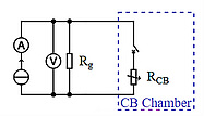
One commonly used resistance-based timing measurement method is derived from the Dynamic Resistance Measurement (DRM). In this approach, the resistance of the contact system is determined during an opening or closing operation by injecting a current (A) and measuring the resulting voltage drop (V) across the circuit breaker’s main contacts. An equivalent circuit for this arrangement is shown in Figure 1. The calculated resistance values (Rm) obtained by this method are also used to determine the operation time of the circuit breaker.
Achieving reliable and highly accurate timing results with the DRM method depends on carefully selecting the threshold resistance values (Rt) based on the ground loop resistance (Rg). It is also essential to know the maximum ground loop resistance at which this method remains applicable, and beyond which it should no longer be used.
Figure 1: Equivalent circuit of a both sides grounded circuit breaker
Validated on modern and legacy circuit breakers
A series of tests were carried out to determine the maximum measurement deviation. Figure 2 illustrates an opening operation and defines the measurement deviation ΔT from the opening time To. Tests performed on circuit breakers equipped with a main and arcing contact system demonstrate that the measurement deviations remain well within the applicable standards.
Figure 2: Determination of timing measurement inaccuracy during opening operation
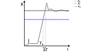
To = Opening time
ΔT = Measurement deviation
Rg = Ground loop resistance
Rt = Threshold value
Rm = Measured resistance value
Want to learn more about measurement results, limitations, and best practices?
Visit us at CIGRE Paris 2026 and join our experts to discuss how safe and accurate timing measurements can be achieved in today's substations.