HIPOT Testing Made Easy

How to perform the voltage withstand test of your GIS with less effort


Substations are increasingly being designed, adapted or expanded with gas-insulated switchgear (GIS). There are various reasons for this trend towards GIS, such as better protection of the system components against aging processes, contamination or corrosion. The associated reduced need for maintenance of the components and the longer service life can be translated into lower operating costs in the long term. Very often, however, the often most important reason is the significantly lower space requirement. A GIS can get by with a fraction of the space required for an air insulated system. Wherever space is either very expensive or simply not available in sufficient quantities, such as in cities, on platforms or underground, GIS are often the only option.
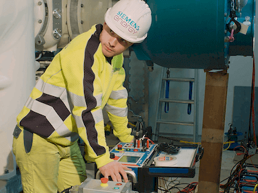
In the applicable standard, the IEC 62271-203, the test is also called power-frequency voltage test. The GIS must be installed completely and gas-filled at rated filling density during the test. If the GIS is extended with new parts, these shall again be subjected to a dielectric test on site. The test is passed if the insulation can withstand the withstand voltage for 60 seconds, with test frequencies ranging from 10 to 300 Hz.
Voltage withstand testing essentials

How high is the applied test voltage?

Typically, testing voltage requirements are aligned with the IEC 62271-203 recommendations, but can be negotiated between client and contractor. Usually, the test voltage used onsite is increased in steps up to a maximum of 80 % of the test voltage used during type testing in the factory, resulting in a voltage still above rated voltage. For instance, the maximum on-site withstand voltage of a 123 kV rated GIS is 200 kV.
Note: Partial discharge measurements can be conducted in the same testing cycle. After the cycle with the highest voltage withstand voltage had been conducted, the test voltage is decreased to the applicable level (148 kV for a 123 kV rated GIS). 

When are HIPOT tests performed?


  • Before commissioning a GIS, as part of the voltage testing (mandatory)
  • After system extensions (mandatory)
  • Following activation of partial discharge monitoring systems and in-service measurements
  • To determine the condition of the insulation in elder systems, following in-service measurements
  •  

Which other tests are performed in parallel?

In most cases, a partial discharge (PD) measurement will be carried out during a HIPOT test, since the high-voltage source is already in place and the insulation of the GIS only has to be subjected to the electrical stress of the high voltage once. The PD measurement can give additional diagnostic information, and, in case of weakened insulation, it will warn testers not to increase the test voltage further.

What are the challenges of conventional HIPOT testing?

A voltage withstand test using conventional methods requires large test components, which are often difficult to use in the cramped conditions around a GIS. In addition, considerable transport costs are incurred for these very heavy components, such as the SF6 transformer with coupling capacitor.

How to prepare the GIS for a test at resonant frequency?

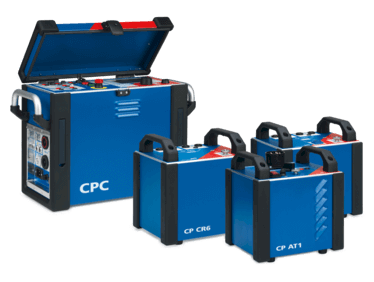
A test at resonant frequency requires a voltage transformer (VT) with reinforced undervoltage winding (PowerVT) installed on the GIS. A permanently installed PowerVT can be used as a VT during normal operation. The somewhat higher costs of the PowerVT are normally amortized with just one additional measurement, since the costs for transport and use of the test transformer are eliminated. However, a PowerVT can also be connected to the GIS only for the duration of the test (please consider sufficient cooling time in between test runs to prevent damage to the PowerVT).

How many sections can be measured with CPC 100 & CP RC2?

The test system needs to compensate the capacitance of the GIS for the high voltage injection via the PowerVT. The more sections there are, the higher is the capacitance to be compensated.
Knowing the capacity of the sections and the nominal ratio of the PowerVT, the required injection power can be determined.
In case the power of one CPC & RC2 set would be insufficient, a second CPC & CP RC2 set can be used to double the power.


Related Products


Discover our Coverstories

Listen to our podcasts

You are using an outdated browser version.
Please upgrade your browser or use another browser to view this page correctly.
×