Our Holistic Solution for Security Incidents and Functional Errors
Many industrial organizations still regard cybersecurity for the company’s IT and OT (Operational Technology) as a unique issue. This is often handled in isolation. While it is true that utility IT departments structurally and functionally vary between protection and SCADA departments, the need for convergence is becoming more critical. In this new era of increased and pervasive cyber threats, a structural change can no longer be viewed as a consideration or option. Quite the opposite: the convergence between the two orbs needs to be a mission-critical goal.
Effective security requires integrating cybersecurity professionals, OT engineers, and support staff through shared learning and a common vocabulary platform.
Our StationGuard Solution
The OMICRON team took the specific processes and priorities that govern an OT environment and combined them with the ability to identify, ingest, and correlate threat data and functional issues to deliver a central management system. This management system is built for the demands of both IT and power engineers.
"It’s time to bring IT and OT teams to a familiar playground."
- Amro Mohamed, Regional Cybersecurity Sales Specialist
Our StationGuard Intrusion Detection System (IDS) detects any prohibited or potentially dangerous traffic in your control center, substation, and power plant system. Engineering files, for example, can be imported to automatically create communication permissions and assign roles to devices based on their purpose. StationGuard, then, triggers an alert that shows all the following: category, source and target, a concise description, as well as the approximate point in time that the event occurred.
To better understand event alerts, security officers and power engineers need to work together. Only the engineers who are responsible for the substation, plant, or control center know what each device is supposed to do, or not to do. The key difference between our solution and others lies in how well these descriptions trace back to the real cause in the power grid. As a result, the protection engineers and IT specialists understand each other when talking about the issue and the devices involved – communication becomes more efficient.
Follow this link to learn about all the benefits of our StationGuard solution and its functionalities:
![]()
Let’s explore the distinctive features of our StationGuard solution. We consider an exemplary scenario of a hijacked historian database server that communicates with malware in a power plant or substation.
Our solution can answer the following questions about every incident:
What security incident happened in your system?
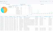
Starting from the GridOps Alerts dashboard , we will investigate an alert that was reported by the StationGuard IDS sensor located at the substation named “Munich North.”
An integral part of our StationGuard solution is the GridOps Alerts dashboard. Its very purpose is to summarize what exactly happened in your system.
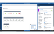
We use the sensor-level view to further investigate the specific alert and its network environment.
Within the dashboard, you can go from the grid-level overview down to the network of your plant, substation, or control center. This will give you a clear image of a specific alert.
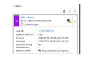
Every alert is contextualized to help you understand the nature of the event and assist you in containing the incident.
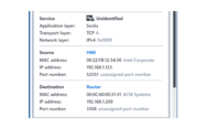
The StationGuard IDS detected an anomalous activity and reported that. The HMI sent unexpected ‘Socks’ network traffic to an external historian database server through the Router in the station. From the perspective in the substation, we see the communication between the HMI and the router to the WAN. The historian database is behind the router. From this perspective, the router is therefore the actor.
You can investigate security and functional issues in real-time by viewing the network level IDS sensor dashboard and our unique network visualization useful for both IT and OT professionals. The message details in the event log provide further information, for example, about the involved device(s), MAC/IP addresses, used applications, protocols, etc.
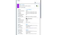
Note: It is quite common to have a connection between HMI and an external historian database. In this system, this connection is based on MySQL and, therefore, a MySQL connection has been allow-listed for the HMI. Now this permission was violated since the communication changed to become a Socks connection using the same port numbers. The cause of this could be a malicious application on the HMI and/or the external historian database. Every time StationGuard displays information about an actor (Router) or victim (HMI) in an alert, it shows the current name of the device, and the top-most identified OSI layer is shown in the alert message. Here it was the “Socks” application that was identified. “Socks” is a proxy application used to redirect communication over a third-party device to facilitate communication through a firewall. This can be useful in the IT environment, but it is also used by attackers to create a tunnel to exfiltrate data or to establish a connection to a command-and-control server. It is likely that this technique was also used in the 2016 Ukraine “Industroyer” cyber attack.
When did the security event occur?
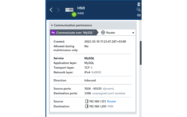
Every alert provides the approximate time of the event and when it was last updated with added information about the activity. Thus, the latter timestamp typically reflects the duration of the activity. This can range from microseconds for inter-device communication to dozens of seconds for, e.g., switchgear commands.
The alert in our system occurred on 2022-05-10 19:43:01.607 UTC offset +03:00.
Quite often alerts are triggered when engineers are present on-site doing maintenance or routine testing. The details also state whether an alert was detected during normal operation or during maintenance.
The activity here happened during normal operation. No engineering team was present on-site when it happened. Hence, “Occurred during maintenance” is set to “No”.
Where in your network did the event take place?
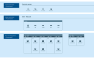
Most notably, GridOps provides us with an asset inventory dashboard that maximizes visibility across the grid. The network diagram (Figure 1) shows us that both the actor and the victim are found at the Station control level, corresponding to the Purdue level 2 as indicated in the below mapping.
By relying on real-time asset inventory and topology mapping, every alert displayed on the GridOps Alerts dashboard will provide information about the source of the event and the site in which the event occurred.
Who was involved in the event?
As StationGuard utilizes an allow-listing approach to detect suspicious or prohibited traffic, we originally defined and approved every communication by all devices in the substation.
This information can be imported into StationGuard, either from the IEC 61850 SCD (Substation Configuration Description) which you can export from engineering tools, or from spreadsheets that document network engineering.
The alert shows us that the traffic is unapproved. We find an internal actor that is associated with the incident. The actor’s IP address is 192.168.1.123 and the target’s IP address is 192.168.1.200.
To enable efficient communication between security officers and protection and SCADA engineers, GridOps displays the engineering names of each asset, instead of mere IP addresses. These engineering names can be imported from engineering files and spreadsheets.
Every alert raised by StationGuard highlights the entities that cause or contribute to the event, what type of assets are involved, who the actor is, and who has been identified as the target(s).
We can now easily read out the voltage level, bay, and equipment names that were involved in the event.
How was the security incident carried out?
We discover that the attacker tried to establish a Socks proxy connection on the same port used for the MySQL connection (TCP port 3306).
Every alert raised by StationGuard will give insights into the nature of the action, how the activity was carried out and what the actor did to cause it. An incident is caused by at least one action, but most will comprise multiple activities.
Why did the IDS raise an alert in the first place?
Some questions remain:
- Why did the IDS raise an alert here?
- Which communication permissions or policies were violated? Why were the communication permissions set in this way?
- Why was this not a legitimate communication of the source device?
StationGuard visualizes which communication is allowed; everything else is prohibited by default. We see that there is a connection allowed between the HMI and the Historian database server through the router. Additionally, the “MySQL” application had been allow-listed for that connection; the alert happened because it is no longer MySQL.
Eventually, the StationGuard Help provides us with possible issues that caused the incident. It provides us with a step-by-step guidance to address all the aforementioned why-questions. The alert is our starting point to investigate. What interests us most at this point are the following questions:
Q: Is it a different connection to a service on a new (server-side) port number or did the application of that same connection change?
A: We find out that the latter is the case here. The destination port number was the same, but the application layer changed from MySQL to Socks. This activity appears suspicious.
Q: Do all corresponding devices have the correct roles assigned to them? Is there a function of this device that was not used until before?
A: This question requires OT knowledge about the device and its purpose. The OT engineers involved confirmed that no outgoing connection is expected from the HMI, except a database connection.
This now leaves the suspicion that the behavior could be caused by malware on the HMI. StationGuard records a network capture of every event. We capture this evidence and approach the HMI vendor.
The context of the alert helps you pinpoint why the incident was possible in the first place. Such information is helpful on many levels – for example, to assess security control flaws and asset vulnerabilities and identify mitigation strategies.
In the fictitious example above, we documented a possible response chain: from the detection of suspicious behavior by an HMI in a substation to the tracing of a malware infection on that HMI device. It illustrated how StationGuard, in combination with GridOps, allows detection, tracing, visualization, and analysis of suspicious behavior in power grid OT networks in a single application. When it comes to determining the what, when, where, who, why, and how behind security incidents, our unified interface enables efficient collaboration between IT officers and OT experts - so that the combined capabilities can be fully leveraged.
Related Screenshots
![]()
Upgrade your StationGuard with our GridOps component
The StationGuard component GridOps is the central solution for providing a holistic view on many operational tasks in the digital power grid, starting with security operations and asset inventory functions in the first release. From analyzing security alerts to asset inventory and vulnerability management, GridOps brings protection engineers and IT specialists together in a one-team application. It allows IT security officers to see grid cybersecurity augmented with OT knowledge and it allows OT engineers to participate in grid cybersecurity operations in a familiar environment.
GridOps Main Functions
GridOps offers powerful functions that aid in power grid security operations. You can ...
- centrally manage all StationGuard IDS sensors and see the current threat status,
- use advanced alert analysis and statistics,
- manage your asset inventory globally and be notified of discovered assets,
- benefit from valuable vulnerability detection and support in your risk management workflows, and
- gain deeper insight with security reports and asset information.
Global Asset Inventory
Easily track all the detected assets and configuration changes and maintain an up-to-date list of assets published by StationGuard sensors across the grid.
Alert Dashboard
Get an overview of the alert status across all sites and visualize your security posture.
Sensor-level Network View
Navigate from a grid-level overview to a specific control center, power plant, or substation network view to gain an overview over the alerts.
Click on the link and discover all the strengths of our GridOps component, which include two additional benefits: Asset Inventory and Vulnerability Management.