
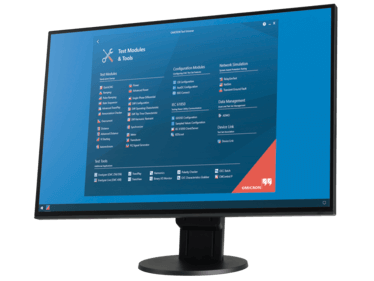
State Sequencer
Determining operating times and logical timing relations by state-based sequences
State Sequencer is a very flexible test module for determining operating times and logical timing sequences. A state is defined by the output conditions (voltages and currents, binary outputs) and a condition for the transition to the next state.
Definition of individual states
Within one state, all configured test signals (voltage and current outputs) of the used test device can be set independently in amplitude, phase, and frequency. Besides the direct input of the individual voltages and currents, the integrated Fault Calculator allows the automatic calculation of the test quantities. These can be entered as fault values, power values, symmetrical components, or impedances (with constant test current, constant test voltage or constant source impedance model).
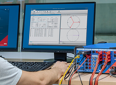
Measurement
Time measurement conditions can be defined to check the correct operation of the relay. Individual response times and tolerances can be specified for each measurement condition, allowing a fully automatic assessment of the results. If the measured time is within the tolerance range, the test is “passed“; otherwise, it is “failed“.
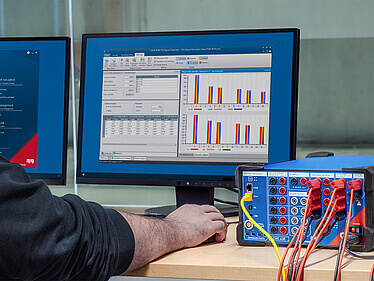
Assessment and reporting
The measurement conditions are displayed in a table. After a test execution this table also contains the actual measured times and deviations and the automatic assessment of the results. The last column contains the “passed“ or “failed“ information. All of the time signals (voltages, currents and binary inputs) can be displayed graphically to aid in studying the reaction of the relay.
Solutions for:

Documents
Literature
Videos
State Sequencer Module
Training
June 23 - 25, 2026
Kolding, Denmark
English
Test Universe, ADMO with InSight, State Sequencer, Pulse Ramping, Ramping, Overcurrent, Advanced Distance, Advanced Differential, OMICRON Control Center, Protection Testing Library (PTL), CMC Swift, CMC Family
July 7 - 9, 2026
Training Center Stafford,
Stafford,
United Kingdom
English
Test Universe, ADMO with InSight, State Sequencer, Pulse Ramping, Ramping, Overcurrent, Advanced Distance, Advanced Differential, OMICRON Control Center, Protection Testing Library (PTL), CMC Swift, CMC Family
To ensure that you receive the highest quality products and enjoy full customer support, please acquire our products exclusively through our authorized sales channels as portrayed on this site.